Cirkit Designer
Your all-in-one circuit design IDE
Home /
Project Documentation
Arduino 101 Light-Activated LED with LDR Sensor
Circuit Documentation
Summary
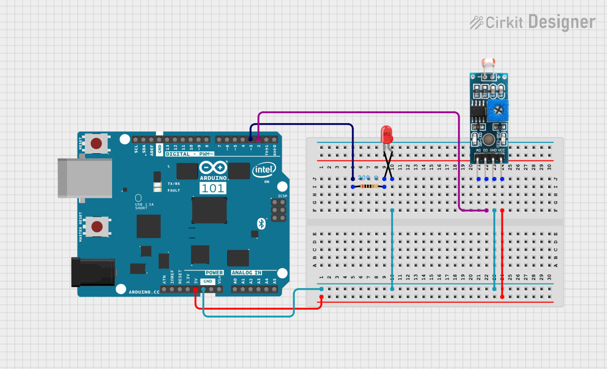
This circuit involves an Arduino 101 microcontroller, a resistor, a red LED, and a Light Dependent Resistor (LDR) module. The circuit is designed to light up the LED when the LDR detects a low light level. The Arduino 101 reads the digital output from the LDR and controls the LED accordingly.
Component List
Arduino 101
- Description: A microcontroller board based on the Intel Curie module.
- Pins: A5/SCL, A4/SDA, AREF, GND, D13/SCK, D12/MISO, D11 PWM/MOSI, D10 PWM/SS, D9 PWM, D8, D7, D6 PWM, D5 PWM, D4, D3 PWM, D2, D1/TX, D0/RX, AIN, ioref, RESET, 3V3, 5V, VIN, A0, A1, A2, A3, ICSP MISO, ICSP SCK, ICSP MOSI
Resistor
- Description: A 200 Ohm resistor.
- Pins: pin1, pin2
- Properties:
- Resistance: 200 Ohms
LED: Two Pin (red)
- Description: A red LED with two pins.
- Pins: cathode, anode
Module LDR
- Description: A Light Dependent Resistor (LDR) module.
- Pins: VCC, GND, DO, AO
Wiring Details
Arduino 101
- D3 PWM is connected to pin1 of the Resistor.
- GND is connected to GND of the Module LDR and cathode of the LED.
- D2 is connected to DO of the Module LDR.
- 5V is connected to VCC of the Module LDR.
Resistor
- pin1 is connected to D3 PWM of the Arduino 101.
- pin2 is connected to anode of the LED.
LED: Two Pin (red)
- cathode is connected to GND of the Arduino 101 and GND of the Module LDR.
- anode is connected to pin2 of the Resistor.
Module LDR
- VCC is connected to 5V of the Arduino 101.
- GND is connected to GND of the Arduino 101 and cathode of the LED.
- DO is connected to D2 of the Arduino 101.
Code Documentation
Arduino 101 Code
void setup() {
  pinMode(2, INPUT);
  pinMode(3, OUTPUT);
}

void loop() {
    if (digitalRead(2) == LOW) {
        digitalWrite(3, HIGH);
    } else {
        digitalWrite(3, LOW);
    }
}
Explanation:
- setup(): This function is called once when the program starts. It sets pin 2 as an input and pin 3 as an output.
- loop(): This function runs continuously after the setup. It reads the digital value from pin 2 (connected to the LDR module). If the value is LOW (indicating low light), it sets pin 3 (connected to the LED) to HIGH, turning the LED on. Otherwise, it sets pin 3 to LOW, turning the LED off.