
Circuit Documentation
Summary of the Circuit
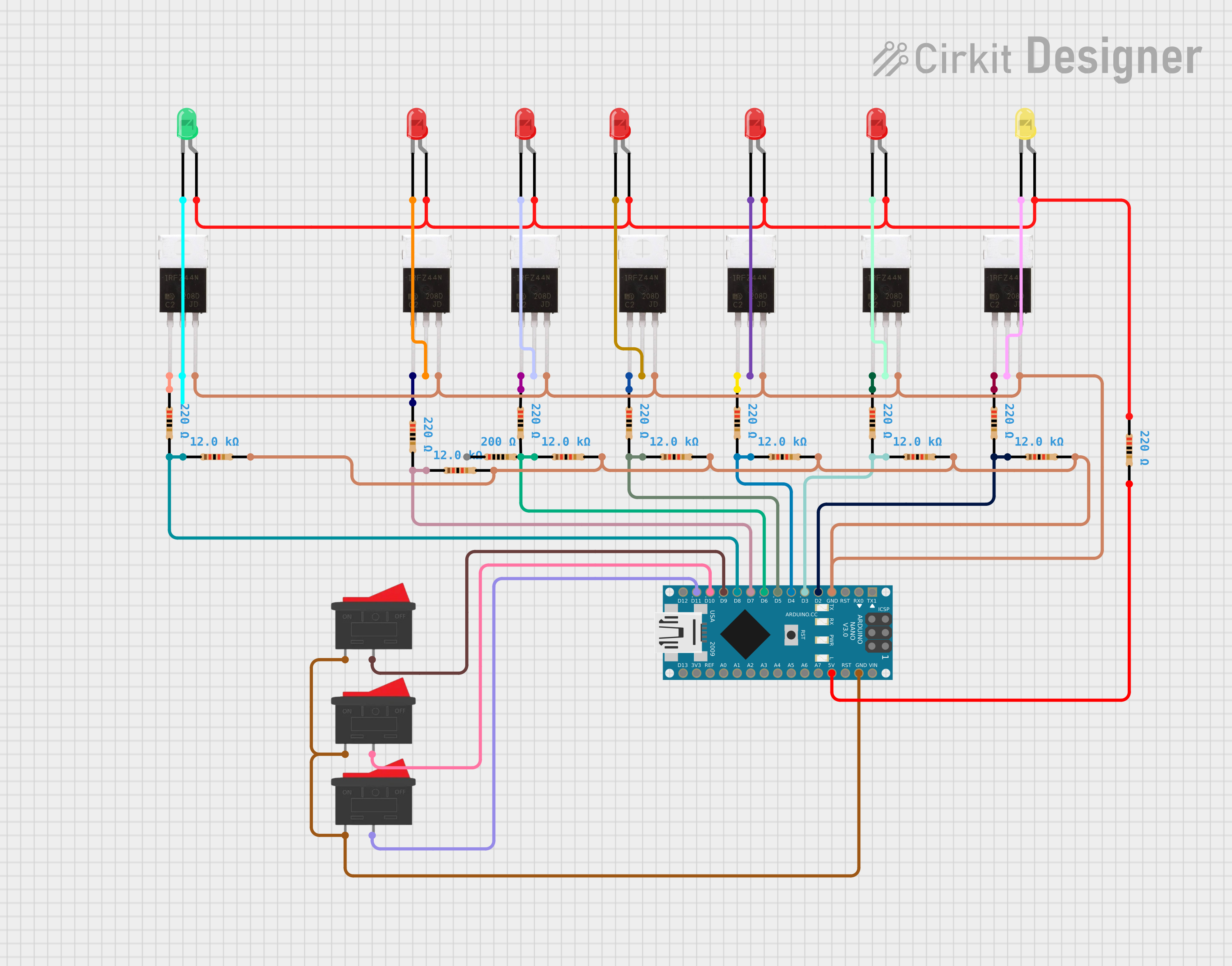
This circuit appears to be designed to control multiple LEDs using an Arduino Nano microcontroller and a series of IRFZ44N power MOSFETs. The MOSFETs are likely used as switches to turn the LEDs on and off. The circuit includes resistors for current limiting and pull-down purposes, as well as rocker switches to control the power flow.
Component List
Microcontrollers
- Arduino Nano: A compact microcontroller board based on the ATmega328P, equipped with a variety of digital and analog I/O pins.
Transistors
- IRFZ44N: A power MOSFET used for switching applications, with three pins: Gate, Drain, and Source.
Resistors
- 220 Ohm Resistors: Used for current limiting to protect LEDs or as pull-down resistors for the MOSFET gates.
- 12k Ohm Resistors: Likely used as pull-down resistors for the MOSFET gates.
- 200 Ohm Resistor: Another current limiting resistor for an LED.
Switches
- Rocker Switches: Used to control the power flow in the circuit.
LEDs
- Red LEDs: Indicators that can be turned on or off by the circuit.
- Green LED: An indicator that can be turned on or off by the circuit.
- Yellow LED: An indicator that can be turned on or off by the circuit.
Wiring Details
Arduino Nano
- Digital Pins (D2-D11/MOSI): Connected to various resistors and switches to control the circuit's logic.
- GND: Connected to the source pins of all IRFZ44N MOSFETs and rocker switches.
- 5V: Connected to the anodes of all LEDs through a current-limiting resistor.
IRFZ44N MOSFETs
- Gate: Connected to the Arduino Nano through a resistor or directly to a rocker switch.
- Drain: Connected to the cathode of an LED.
- Source: Connected to the ground (GND) of the circuit.
Resistors
- 220 Ohm and 200 Ohm Resistors: Connected between the Arduino Nano and the gate of a MOSFET or between the anode of an LED and the 5V supply.
- 12k Ohm Resistors: Connected between the gate of a MOSFET and ground, serving as pull-down resistors.
Rocker Switches
- Pin 1: Connected to the ground (GND) of the circuit.
- Pin 2: Connected to the digital pins of the Arduino Nano.
LEDs
- Anode: Connected to the 5V supply through a current-limiting resistor.
- Cathode: Connected to the drain of a MOSFET.
Documented Code
void setup() {
  // put your setup code here, to run once:

}

void loop() {
  // put your main code here, to run repeatedly:

}
The provided code is a template with empty setup() and loop() functions. The setup() function is intended to contain initialization code that runs once when the microcontroller is powered on or reset. The loop() function is meant to contain the main logic of the program, which runs repeatedly as long as the microcontroller is powered.
To control the LEDs and read the state of the rocker switches, the code should be expanded to configure the digital pins connected to the switches as inputs and the pins connected to the MOSFET gates as outputs. Digital write operations can then be used to turn the LEDs on and off based on the state of the switches or other logic.