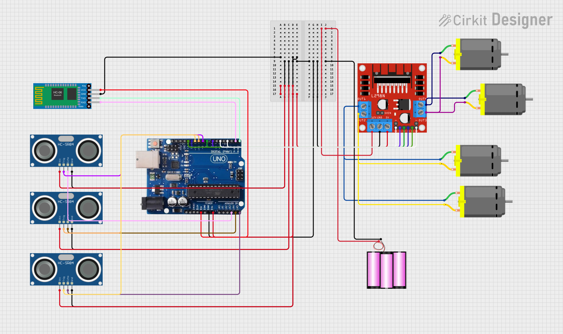
Arduino-Controlled Bluetooth Robotic Vehicle with Ultrasonic Sensors

Circuit Documentation
Summary
The circuit in question appears to be designed for controlling multiple DC motors, interfacing with ultrasonic sensors, and providing Bluetooth connectivity, likely for a robotics or automation application. The circuit is powered by a 12V battery and uses an Arduino Uno R3 as the central microcontroller unit. The Arduino controls the DC motors through an L298N motor driver and reads distance measurements from HC-SR04 ultrasonic sensors. A Bluetooth HC-06 module is included for wireless communication.
Component List
DC Motor
- Description: A standard DC motor used for converting electrical energy into mechanical rotation.
- Purpose: Typically used for driving wheels or other rotating parts in a robotics application.
Battery 12V
- Description: A 12-volt battery that provides the power source for the circuit.
- Purpose: Supplies electrical power to the motor driver and indirectly to the motors and other components.
HC-SR04 Ultrasonic Sensor
- Description: An ultrasonic distance sensor that can measure distances by emitting ultrasonic waves and measuring the time it takes for the echo to return.
- Purpose: Used for distance measurement or object detection in robotics and automation.
Arduino Uno R3
- Description: A microcontroller board based on the ATmega328P, with digital and analog I/O pins.
- Purpose: Acts as the brain of the circuit, controlling the motors and reading sensor data.
L298N DC Motor Driver
- Description: A dual H-bridge motor driver capable of driving two DC motors or one stepper motor.
- Purpose: Used to control the direction and speed of the DC motors.
Bluetooth HC-06
- Description: A Bluetooth module that allows for wireless communication with other Bluetooth-enabled devices.
- Purpose: Enables wireless control or data transmission for the circuit.
Wiring Details
DC Motor
- Connections:
pin 1andpin 2are connected to the outputs of the L298N motor driver.
Battery 12V
- Connections:
+is connected to the 12V input of the L298N motor driver.-is connected to the ground (GND) net of the circuit.
HC-SR04 Ultrasonic Sensor
- Connections:
VCCis connected to the 5V output from the Arduino Uno R3.GNDis connected to the ground (GND) net of the circuit.TRIGandECHOpins are connected to specific I/O pins on the Arduino Uno R3 for triggering the sensor and reading the echo.
Arduino Uno R3
- Connections:
GNDis connected to the ground (GND) net of the circuit.VINis connected to the 5V net, which powers the ultrasonic sensors and the motor driver logic.- Digital I/O pins are connected to the L298N motor driver control inputs and the HC-SR04 sensor trigger and echo pins.
RXandTXpins are connected to the Bluetooth HC-06 module for serial communication.
L298N DC Motor Driver
- Connections:
12Vis connected to the positive terminal of the 12V battery.GNDis connected to the ground (GND) net of the circuit.5Vis connected to the 5V net, which powers the logic of the motor driver.ENA,ENB,IN1,IN2,IN3, andIN4are connected to specific I/O pins on the Arduino Uno R3 for motor control.OUT1,OUT2,OUT3, andOUT4are connected to the DC motors.
Bluetooth HC-06
- Connections:
VCCis connected to the 5V output from the Arduino Uno R3.GNDis connected to the ground (GND) net of the circuit.TXDandRXDare connected to theRXandTXpins of the Arduino Uno R3 for serial communication.
Documented Code
No code was provided for the microcontrollers in the circuit. To fully utilize the circuit's capabilities, embedded code for the Arduino Uno R3 would be required to control the motors via the L298N driver, read data from the HC-SR04 ultrasonic sensors, and handle Bluetooth communication with the HC-06 module.