
Capacitive Force Sensor Data Acquisition System with Flex Resistors
View and Edit Project In Cirkit Designer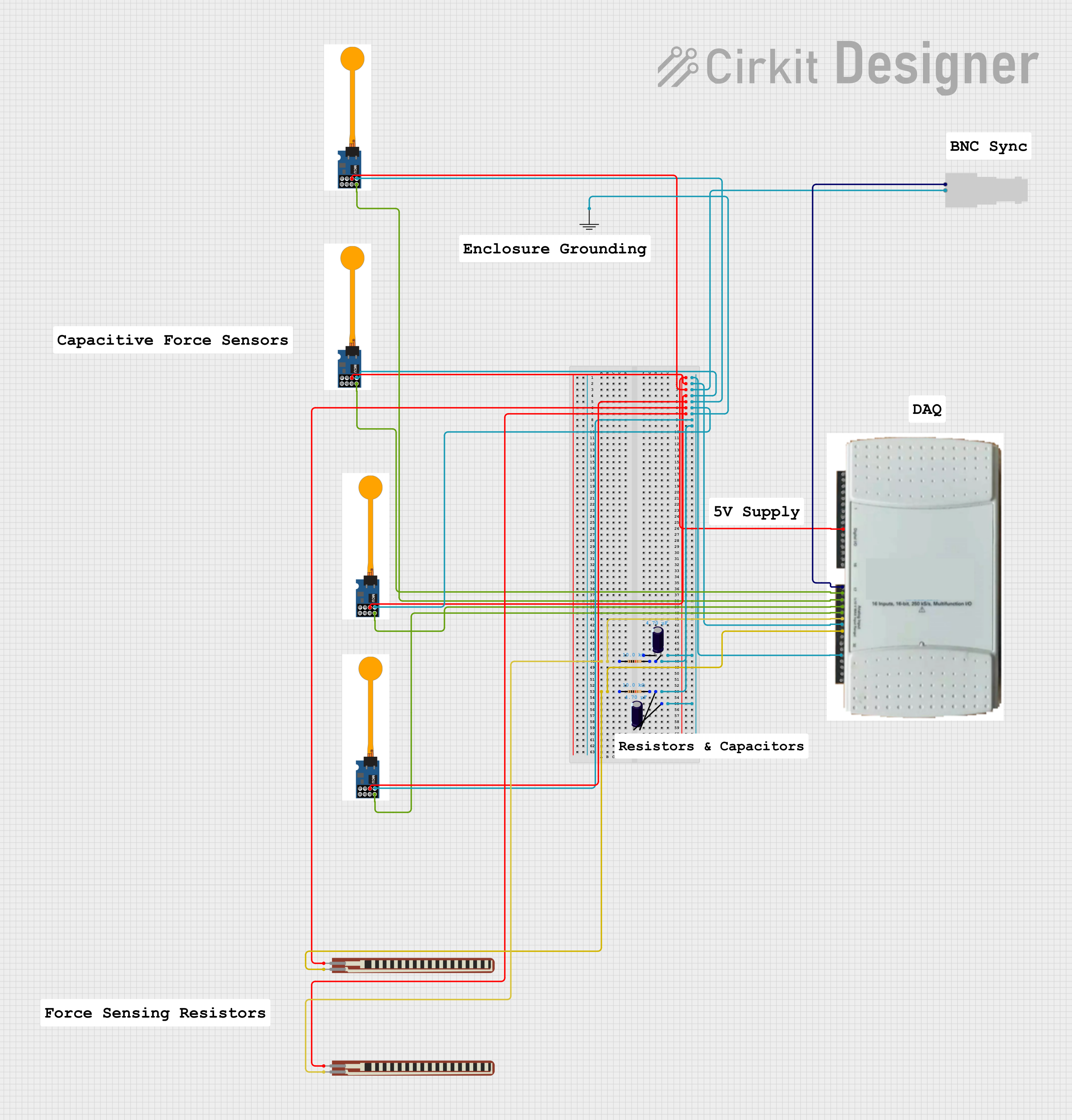
Circuit Documentation
Summary
This document provides a detailed overview of a circuit that includes various components such as a Data Acquisition (DAQ) system, capacitive force sensors, resistors, capacitors, and connectors. The circuit is designed to measure and process signals from multiple sensors and transmit the data through a DAQ system. The document includes a component list, wiring details, and code documentation.
Component List
DAQ
- Description: Data Acquisition system
- Pins: 32 pins labeled from 1 to 32
Capacitive Force Sensor
- Description: Sensor to measure force capacitively
- Pins: 8 pins labeled 1, 2, 3, 4, 5, 6, 7, 8
Female BNC
- Description: Female BNC connector
- Pins: 2 pins labeled Pin 1, Pin 2
GND
- Description: Ground connection
- Pins: 1 pin labeled GND
Resistor
- Description: Resistor with a resistance of 10k Ohms
- Pins: 2 pins labeled pin1, pin2
2.2 inch Basic Flex Resistor
- Description: Flexible resistor
- Pins: 2 pins labeled Pin 2, pin 1
Electrolytic Capacitor
- Description: Capacitor with a capacitance of 4.7 µF
- Pins: 2 pins labeled +, -
Wiring Details
DAQ
- Pin 10: Connected to pin 6 of all capacitive force sensors
- Pin 17: Connected to Pin 1 of the Female BNC
- Pin 18: Connected to pin 4 of one capacitive force sensor
- Pin 19: Connected to pin 4 of another capacitive force sensor
- Pin 20: Connected to pin 4 of another capacitive force sensor
- Pin 21: Connected to pin 4 of another capacitive force sensor
- Pin 22: Connected to pin 1 of a resistor and pin 1 of a 2.2 inch basic flex resistor
- Pin 23: Connected to pin 5 of all capacitive force sensors
- Pin 24: Connected to pin 1 of another resistor and pin 1 of another 2.2 inch basic flex resistor
- Pin 28: Connected to pin 5 of all capacitive force sensors
Capacitive Force Sensor
- Pin 4: Connected to DAQ pins 18, 19, 20, and 21
- Pin 5: Connected to DAQ pins 23 and 28
- Pin 6: Connected to DAQ pin 10
Female BNC
- Pin 1: Connected to DAQ pin 17
- Pin 2: Connected to pin 5 of all capacitive force sensors
GND
- GND: Connected to pin 5 of all capacitive force sensors
Resistor
- Pin 1: Connected to DAQ pin 22 and pin 1 of a 2.2 inch basic flex resistor
- Pin 2: Connected to pin 2 of an electrolytic capacitor
- Pin 1: Connected to DAQ pin 24 and pin 1 of another 2.2 inch basic flex resistor
- Pin 2: Connected to pin 2 of another electrolytic capacitor
2.2 inch Basic Flex Resistor
- Pin 1: Connected to DAQ pin 22 and pin 1 of a resistor
- Pin 2: Connected to pin 6 of all capacitive force sensors
- Pin 1: Connected to DAQ pin 24 and pin 1 of another resistor
- Pin 2: Connected to pin 6 of all capacitive force sensors
Electrolytic Capacitor
- + Pin: Connected to pin 2 of a resistor
- - Pin: Connected to pin 2 of another resistor
- + Pin: Connected to pin 2 of another resistor
- - Pin: Connected to pin 2 of another resistor
Code Documentation
No microcontroller code is provided for this circuit.
This document provides a comprehensive overview of the circuit, including a detailed component list and wiring details. The circuit is designed to measure and process signals from multiple sensors and transmit the data through a DAQ system.