Cirkit Designer
Your all-in-one circuit design IDE
Home /
Project Documentation
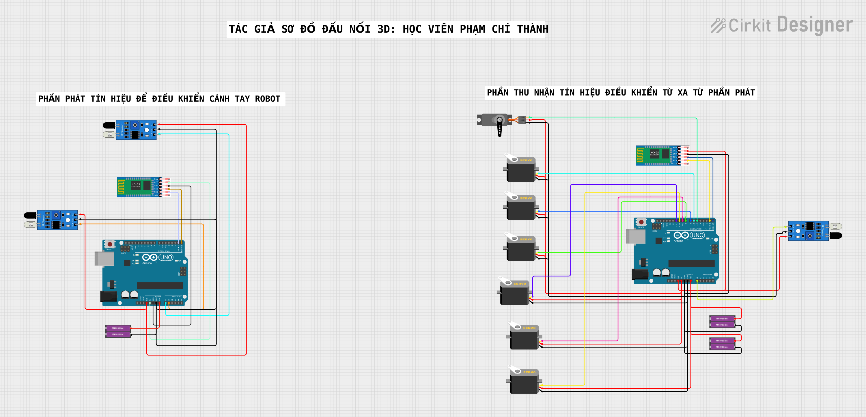
Bluetooth-Controlled Robotic System with IR Sensor Feedback
Circuit Documentation
Summary
The circuit in question appears to be a control system utilizing multiple servos, IR sensors, HC-05 Bluetooth modules, and Arduino UNO microcontrollers. The servos are likely used for actuation purposes, the IR sensors for detecting objects or receiving signals, and the HC-05 modules for wireless communication. The Arduinos serve as the central processing units, interfacing with the sensors, controlling the servos, and managing Bluetooth communication. The circuit is powered by 18650 Li-ion batteries.
Component List
Microcontrollers
- Arduino UNO: A microcontroller board based on the ATmega328P. It has 14 digital input/output pins, 6 analog inputs, a 16 MHz quartz crystal, a USB connection, a power jack, an ICSP header, and a reset button.
Communication Modules
- HC-05 Bluetooth Module: A wireless communication device used for serial communication over Bluetooth. It has pins for enabling the device, power supply, ground, and TX/RX for serial data.
Sensors
- IR Sensor: An infrared sensor capable of detecting obstacles or receiving IR signals. It has pins for output signal, ground, and power supply.
Actuators
- Servo: An actuator capable of precise control of angular position. It has pins for ground, power supply, and control signal (either pulse or PWM).
Power Sources
- 18650 Li-ion Battery x 2: A power source consisting of two lithium-ion batteries. It has terminals for positive and negative voltage supply.
Miscellaneous
- Comment: A placeholder for additional notes or comments in the circuit design.
Wiring Details
Arduino UNO
- Power Supply: Connected to 3.3V and 5V pins for powering other components.
- Ground: Connected to GND pins for a common ground reference.
- Digital Pins: Connected to TX/RX of HC-05 for serial communication and control pins of servos for actuation.
- Analog Pins: Connected to the output of IR sensors for signal detection.
HC-05 Bluetooth Module
- VCC: Powered by 3.3V or 5V from Arduino UNO.
- GND: Connected to the common ground.
- TXD/RXD: Cross-connected to RX/TX pins of Arduino UNO for serial communication.
IR Sensor
- VCC: Powered by 3.3V from Arduino UNO.
- GND: Connected to the common ground.
- OUT: Connected to analog pins of Arduino UNO for signal detection.
Servo
- VCC: Powered by 5V from Arduino UNO or directly from the 18650 Li-ion batteries.
- GND: Connected to the common ground.
- Pulse/PWM: Connected to digital pins of Arduino UNO for control signals.
18650 Li-ion Battery x 2
- +: Provides positive voltage to Arduino UNO's Vin pin and servos.
- -: Connected to the common ground.
Documented Code
Arduino UNO (First Instance)
void setup() {
  // put your setup code here, to run once:

}

void loop() {
  // put your main code here, to run repeatedly:

}
Arduino UNO (Second Instance)
void setup() {
  // put your setup code here, to run once:

}

void loop() {
  // put your main code here, to run repeatedly:

}
Note: The provided code for both Arduino UNO instances is a template with empty setup and loop functions. The actual implementation code for initializing components and defining the main behavior of the circuit is not provided.