
Battery-Powered Raspberry Pi Zero with OLED Display and EmStat Pico for Portable Data Acquisition
View and Edit Project In Cirkit Designer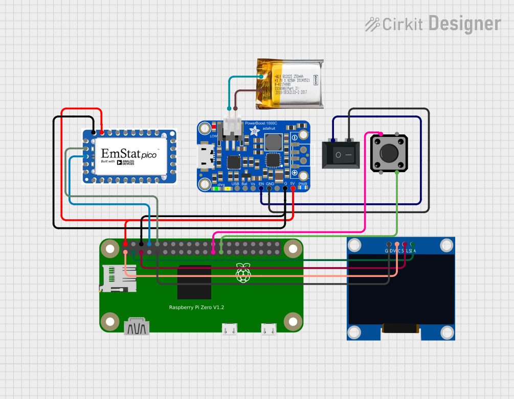
Circuit Documentation
Summary
This document provides a detailed overview of a circuit that integrates a Raspberry Pi Zero, an Adafruit PowerBoost 1000C, a 3.7V LiPo battery, a tactile switch button, an EmStat Pico, a rocker switch, a 128x64 OLED display, and a JST PH 2.0 connector. The circuit is designed to power the Raspberry Pi Zero and other components, provide user input through a tactile switch, and display information on an OLED screen. The EmStat Pico is used for additional functionalities, and the entire system is powered by a LiPo battery managed by the PowerBoost 1000C.
Component List
Raspberry Pi Zero
- Description: A small, affordable computer that can be used for a variety of applications.
- Pins: 5V, 3.3V, GPIO2 (SDA), GND, GPIO3 (SCL), GPIO14, GPIO4, GPIO15, GPIO18, GPIO17, GPIO27, GPIO23, GPIO22, GPIO24, GPIO10, GPIO25, GPIO9, GPIO8, GPIO11, GPIO7, ID_SC, ID_SD, GPIO5, GPIO12, GPIO6, GPIO13, GPIO16, GPIO19, GPIO20, GPIO26, GPIO21
Adafruit PowerBoost 1000C
- Description: A power management module that boosts a 3.7V LiPo battery to 5V.
- Pins: D+, D-, GND, 5.0V, VBUS, VLIPO, VBAT, ENABLE, LBO
3.7V LiPo Battery
- Description: A rechargeable lithium polymer battery.
- Pins: +Ve, GND
Tactile Switch Button - 12mm Square
- Description: A push-button switch used for user input.
- Pins: 3, 1, 4, 2
EmStat Pico
- Description: A small, powerful electrochemical interface for various applications.
- Pins: DGND, V_IN (3.5V - 5.5V), I2C_SDA, I2C_SCL, GPIO_7/WAKE, GPIO_6/CD, GPIO_5, Ain_0, Ain_1, Ain_2, CE_0, WE_0, RE_0, AGND, RE_1, WE_1, CE_1, GPIO_4/SPL_CS0, GPIO_3/SPI_MOSI, GPIO_2/SPI_CLK, GPIO_1/SPI_MISO, GPIO_0/PWM, /RST, /DWN, TX, RX, N/C
Rocker Switch (SPST)
- Description: A single-pole single-throw switch used to control power.
- Pins: 1, 2
128x64 OLED Display (I2C IIC SPI Serial)
- Description: A small OLED display for visual output.
- Pins: GND, SDA, SCL, VCC
JST PH 2.0 Connector
- Description: A connector for the LiPo battery.
- Pins: 1, 2
Wiring Details
Raspberry Pi Zero
- 5V connected to V_IN (3.5V - 5.5V) of EmStat Pico and 5.0V of Adafruit PowerBoost 1000C
- 3.3V connected to VCC of 128x64 OLED Display
- GPIO2 (SDA) connected to SDA of 128x64 OLED Display
- GND connected to DGND of EmStat Pico, GND of Adafruit PowerBoost 1000C, GND of 128x64 OLED Display, and GND of Tactile Switch Button
- GPIO3 (SCL) connected to SCL of 128x64 OLED Display
- GPIO14 connected to TX of EmStat Pico
- GPIO15 connected to RX of EmStat Pico
- GPIO11 connected to 1 of Tactile Switch Button
Adafruit PowerBoost 1000C
- 5.0V connected to 5V of Raspberry Pi Zero and V_IN (3.5V - 5.5V) of EmStat Pico
- GND connected to GND of Raspberry Pi Zero, DGND of EmStat Pico, GND of 128x64 OLED Display, and GND of Rocker Switch
- ENABLE connected to 1 of Rocker Switch
3.7V LiPo Battery
- +Ve connected to 1 of JST PH 2.0 Connector
- GND connected to 2 of JST PH 2.0 Connector
Tactile Switch Button - 12mm Square
- 1 connected to GPIO11 of Raspberry Pi Zero
- 4 connected to GND of Raspberry Pi Zero
EmStat Pico
- V_IN (3.5V - 5.5V) connected to 5V of Raspberry Pi Zero and 5.0V of Adafruit PowerBoost 1000C
- DGND connected to GND of Raspberry Pi Zero and GND of Adafruit PowerBoost 1000C
- TX connected to GPIO14 of Raspberry Pi Zero
- RX connected to GPIO15 of Raspberry Pi Zero
Rocker Switch (SPST)
- 1 connected to ENABLE of Adafruit PowerBoost 1000C
- 2 connected to GND of Adafruit PowerBoost 1000C
128x64 OLED Display (I2C IIC SPI Serial)
- VCC connected to 3.3V of Raspberry Pi Zero
- SDA connected to GPIO2 (SDA) of Raspberry Pi Zero
- SCL connected to GPIO3 (SCL) of Raspberry Pi Zero
- GND connected to GND of Raspberry Pi Zero
JST PH 2.0 Connector
- 1 connected to +Ve of 3.7V LiPo Battery
- 2 connected to GND of 3.7V LiPo Battery
Code
No code is provided for this circuit.