
Arduino Nano-Based Haptic Navigation Shoe for the Visually Impaired with Bluetooth Connectivity
View and Edit Project In Cirkit Designer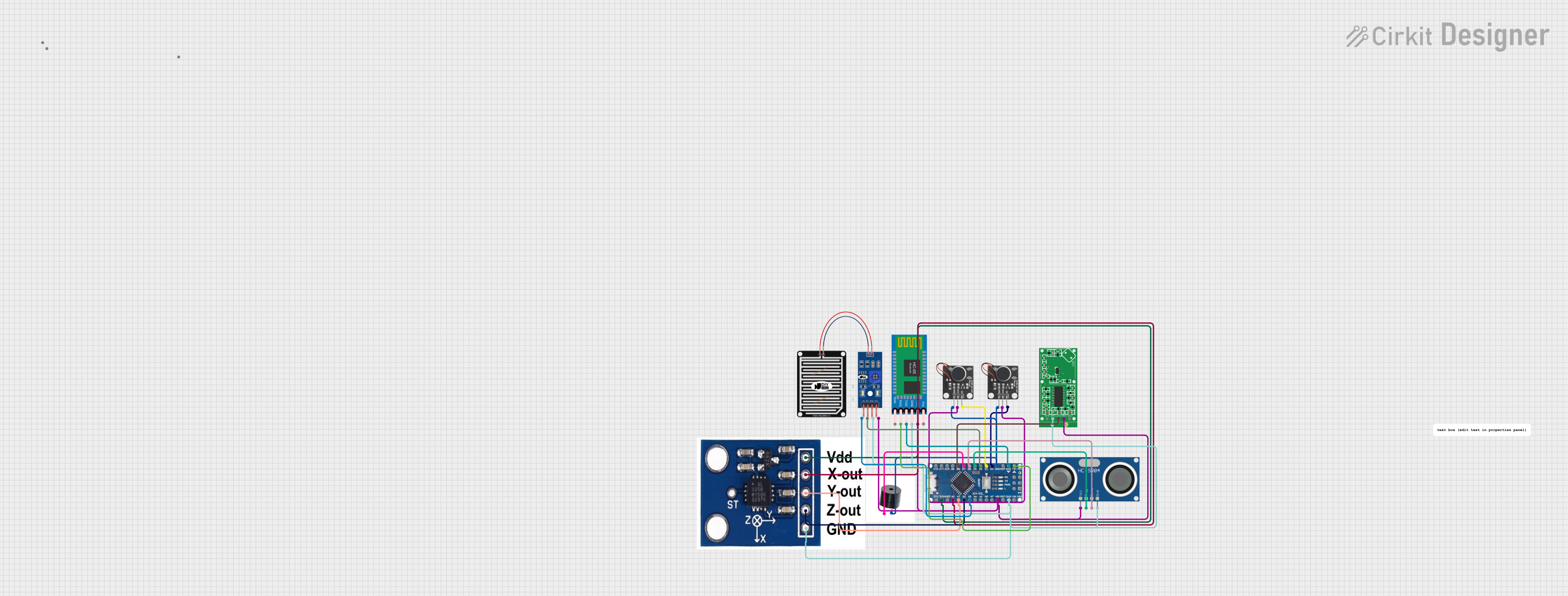
Haptic Navigation Shoe for the Visually Impaired
Summary
This project involves the design and implementation of a haptic navigation shoe for the visually impaired. The system integrates various sensors and actuators, including a water sensor, vibration motors, an ultrasonic sensor, a Bluetooth module, an accelerometer, a radar sensor, and a buzzer. The data from these sensors is processed by an Arduino Nano microcontroller and sent to a mobile app via Bluetooth for tracking and alerts.
Component List
PWM Vibration Motor Sensor Module Switch
- Pins: Signal, Vcc, Ground
- Description: Provides haptic feedback through vibration.
ADXXL335
- Pins: VCC, X-OUT, Y-OUT, Z-OUT, GND
- Description: 3-axis accelerometer for motion detection.
RAIN SENSOR
- Pins: AO, DO, GRD, VCC
- Description: Detects the presence of water.
HC-SR04 Ultrasonic Sensor
- Pins: VCC, TRIG, ECHO, GND
- Description: Measures distance using ultrasonic waves.
HC-05 Bluetooth Module
- Pins: Key, VCC, TXD, RXD, State, GND
- Description: Enables wireless communication with a mobile app.
PWM Vibration Motor Sensor Module Switch
- Pins: Signal, Vcc, Ground
- Description: Provides haptic feedback through vibration.
Buzzer
- Pins: +, GND
- Description: Emits sound alerts.
RCWL-0516 Microwave Radar Motion Sensor Module
- Pins: CDS, VIN, OUT, GND, 3V3
- Description: Detects motion using microwave radar.
Arduino Nano
- Pins: D12, D11, D10, D9, D8, D7, D6, D5, D4, D3, D2, GND, D13, 3V3, AREF, A0, A1, A2, A3, A4 sda, A5 scl, A6, A7, 5V, RST, VIN, RX0, TX1, 13, 11, 12
- Description: Microcontroller for processing sensor data and controlling actuators.
Wiring Details
PWM Vibration Motor Sensor Module Switch
- Signal connected to D3 of Arduino Nano.
- Vcc connected to 5V of Arduino Nano.
- Ground connected to GND of Arduino Nano.
ADXXL335
- VCC connected to 3V3 of Arduino Nano.
- X-OUT connected to A0 of Arduino Nano.
- Y-OUT connected to A1 of Arduino Nano.
- Z-OUT connected to A2 of Arduino Nano.
- GND connected to GND of Arduino Nano.
RAIN SENSOR
- VCC connected to 5V of Arduino Nano.
- GRD connected to GND of Arduino Nano.
- AO connected to A3 of Arduino Nano.
- DO connected to D4 of Arduino Nano.
HC-SR04 Ultrasonic Sensor
- VCC connected to 5V of Arduino Nano.
- TRIG connected to D5 of Arduino Nano.
- ECHO connected to D6 of Arduino Nano.
- GND connected to GND of Arduino Nano.
HC-05 Bluetooth Module
- VCC connected to 5V of Arduino Nano.
- TXD connected to RX0 of Arduino Nano.
- RXD connected to TX1 of Arduino Nano.
- GND connected to GND of Arduino Nano.
PWM Vibration Motor Sensor Module Switch
- Signal connected to D2 of Arduino Nano.
- Vcc connected to 5V of Arduino Nano.
- Ground connected to GND of Arduino Nano.
Buzzer
- + connected to D7 of Arduino Nano.
- GND connected to GND of Arduino Nano.
RCWL-0516 Microwave Radar Motion Sensor Module
- VIN connected to 5V of Arduino Nano.
- OUT connected to D8 of Arduino Nano.
- GND connected to GND of Arduino Nano.
Documented Code
/*
 * Haptic Navigation Shoe for the Visually Impaired
 * This Arduino sketch interfaces with various sensors and actuators to provide
 * navigation and alert mechanisms for the visually impaired. The system includes
 * a water sensor, vibration motors, ultrasonic sensor, Bluetooth module,
 * accelerometer, radar sensor, and a buzzer. The data from the sensors is sent
 * to a mobile app via Bluetooth for tracking and alerts.
 */

// Pin definitions
const int vibrationMotor1Pin = 2;
const int vibrationMotor2Pin = 3;
const int rainSensorAnalogPin = A3;
const int rainSensorDigitalPin = 4;
const int ultrasonicTrigPin = 5;
const int ultrasonicEchoPin = 6;
const int radarSensorPin = 8;
const int buzzerPin = 7;

// Thresholds
const int waterLevelThreshold = 500; // Example threshold for water sensor
const int distanceThreshold = 30; // Example threshold for ultrasonic sensor

void setup() {
  // Initialize serial communication
  Serial.begin(9600);

  // Initialize pins
  pinMode(vibrationMotor1Pin, OUTPUT);
  pinMode(vibrationMotor2Pin, OUTPUT);
  pinMode(rainSensorAnalogPin, INPUT);
  pinMode(rainSensorDigitalPin, INPUT);
  pinMode(ultrasonicTrigPin, OUTPUT);
  pinMode(ultrasonicEchoPin, INPUT);
  pinMode(radarSensorPin, INPUT);
  pinMode(buzzerPin, OUTPUT);
}

void loop() {
  // Read water sensor
  int waterLevel = analogRead(rainSensorAnalogPin);
  if (waterLevel > waterLevelThreshold) {
    digitalWrite(buzzerPin, HIGH); // Activate buzzer
  } else {
    digitalWrite(buzzerPin, LOW); // Deactivate buzzer
  }

  // Read ultrasonic sensor
  long duration, distance;
  digitalWrite(ultrasonicTrigPin, LOW);
  delayMicroseconds(2);
  digitalWrite(ultrasonicTrigPin, HIGH);
  delayMicroseconds(10);
  digitalWrite(ultrasonicTrigPin, LOW);
  duration = pulseIn(ultrasonicEchoPin, HIGH);
  distance = (duration / 2) / 29.1;
  if (distance < distanceThreshold) {
    digitalWrite(vibrationMotor1Pin, HIGH); // Activate vibration motor
  } else {
    digitalWrite(vibrationMotor1Pin, LOW); // Deactivate vibration motor
  }

  // Read radar sensor
  int radarState = digitalRead(radarSensorPin);
  if (radarState == HIGH) {
    digitalWrite(buzzerPin, HIGH); // Activate buzzer
  } else {
    digitalWrite(buzzerPin, LOW); // Deactivate buzzer
  }

  // Send data via Bluetooth
  Serial.print("Water Level: ");
  Serial.println(waterLevel);
  Serial.print("Distance: ");
  Serial.println(distance);
  Serial.print("Radar State: ");
  Serial.println(radarState);

  delay(1000); // Delay for stability
}
This documentation provides a comprehensive overview of the circuit, including a summary, component list, wiring details, and the embedded code used in the project.