
Arduino-Controlled Robotics Interface with IR Sensing and Stepper Motor
View and Edit Project In Cirkit Designer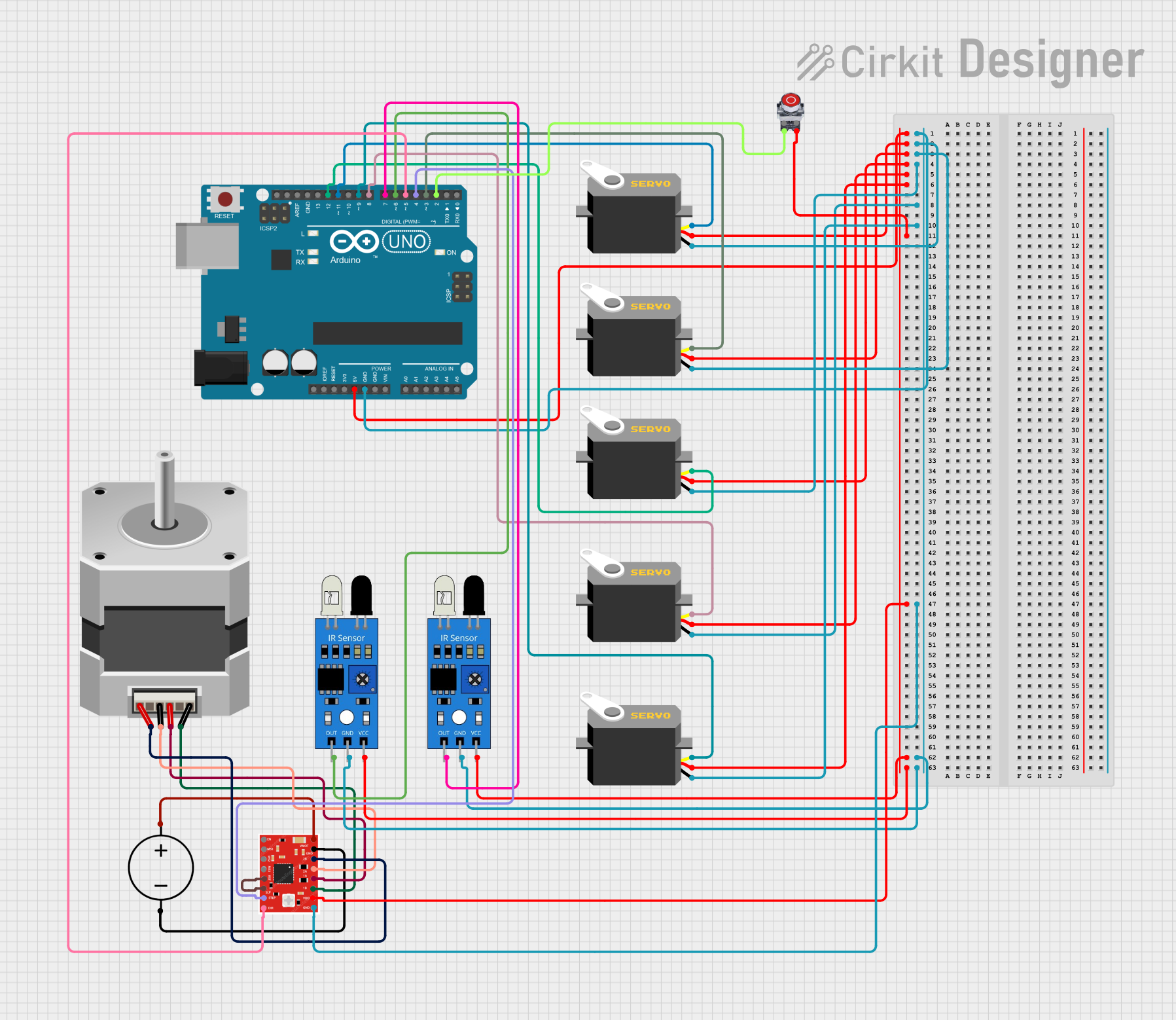
Circuit Documentation
Summary
The circuit in question is designed to interface an Arduino UNO microcontroller with multiple servos, an IR sensor, a stepper motor with its driver, and a pushbutton. The Arduino UNO is used as the central processing unit to control the servos based on the input from the IR sensors and the pushbutton. The stepper motor is driven by the A988 driver, which is also controlled by the Arduino UNO. The circuit is powered by a DC power source that supplies power to the servos, the stepper motor driver, and the IR sensors through the Arduino's voltage regulators.
Component List
Arduino UNO
- Microcontroller board based on the ATmega328P
- It has 14 digital input/output pins, 6 analog inputs, a 16 MHz quartz crystal, a USB connection, a power jack, an ICSP header, and a reset button.
IR Sensor (x2)
- An infrared sensor capable of detecting obstacles and measuring distances.
- It has an output pin that goes high when an obstacle is detected within its range.
Servo (x5)
- A rotary actuator or linear actuator that allows for precise control of angular or linear position, velocity, and acceleration.
- It consists of a suitable motor coupled to a sensor for position feedback.
Stepper Motor (Bipolar)
- A stepper motor that moves in discrete steps, used for precise positioning with a controlled stepping.
- It has four wires corresponding to two electromagnet coils.
A988 DRIVER
- A stepper motor driver that allows the Arduino to drive the bipolar stepper motor.
- It has multiple control pins for direction, step, and enabling/disabling the driver.
Pushbutton STOP
- A normally open pushbutton used to send a signal to the Arduino when pressed.
- It can be used as an emergency stop or a regular input to control the circuit.
DC Power Source
- Provides the power required for the circuit.
- It has a positive and a ground connection to power the components.
Wiring Details
Arduino UNO
5Vpin connected to the VCC of all servos, both IR sensors, the VDD of the A988 DRIVER, and the NO pin of the Pushbutton STOP.GNDpin connected to the GND of all servos, both IR sensors, and the GND of the A988 DRIVER.- Digital pins
D2toD12are used to interface with the servos, IR sensors, and the A988 DRIVER.
IR Sensor
VCCpin connected to the 5V supply from the Arduino.GNDpin connected to the ground of the Arduino.OUTpin connected to digital pinsD6andD7of the Arduino for the two sensors.
Servo
VCCpin connected to the 5V supply from the Arduino.GNDpin connected to the ground of the Arduino.PULSEpin connected to digital pinsD3,D8,D9,D11, andD12of the Arduino for the five servos.
Stepper Motor (Bipolar)
D,B,C,Apins connected to the1B,1A,2A,2Bpins of the A988 DRIVER respectively.
A988 DRIVER
VMOTpin connected to the Positive of the DC Power Source.GNDpin connected to the Ground of the DC Power Source.VDDpin connected to the 5V supply from the Arduino.DIRandSTEPpins connected to digital pinsD5andD4of the Arduino.RSTandSLPpins are interconnected.
Pushbutton STOP
NOpin connected to the digital pinD2of the Arduino and to the 5V supply from the Arduino.
DC Power Source
Positiveconnected to theVMOTof the A988 DRIVER.Groundconnected to theGNDof the A988 DRIVER.
Documented Code
void setup() {
  // put your setup code here, to run once:

}

void loop() {
  // put your main code here, to run repeatedly:

}
The provided code is a template with empty setup() and loop() functions. The setup() function is intended for initialization code that runs once at the start of the program, while the loop() function contains the main logic that runs repeatedly. Specific functionality must be implemented within these functions to control the servos, read from the IR sensors, and manage the stepper motor via the A988 DRIVER based on the circuit's requirements.