Cirkit Designer
Your all-in-one circuit design IDE
Home /
Project Documentation
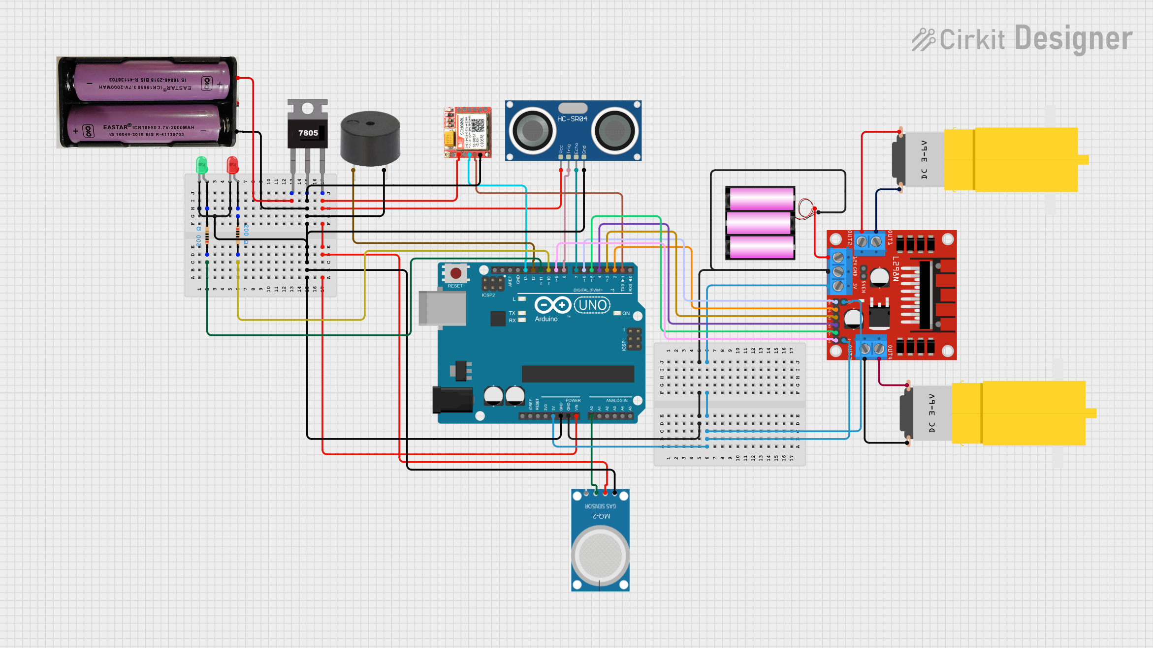
Arduino UNO-Based Smart Robot with Ultrasonic Sensor and GSM Module
Circuit Documentation
Summary
This document provides a detailed overview of a circuit design that includes an Arduino UNO microcontroller, various sensors, a motor driver, and other components. The circuit is designed to interface with multiple peripherals and control motors, sensors, and indicators. The document includes a component list, wiring details, and the embedded code used in the microcontroller.
Component List
Arduino UNO
- Description: Microcontroller board based on the ATmega328P.
- Pins: UNUSED, IOREF, Reset, 3.3V, 5V, GND, Vin, A0, A1, A2, A3, A4, A5, SCL, SDA, AREF, D13, D12, D11, D10, D9, D8, D7, D6, D5, D4, D3, D2, D1, D0
7805
- Description: Voltage regulator that outputs 5V.
- Pins: Vin, Gnd, Vout
7.4v Battery
- Description: Power source providing 7.4V.
- Pins: +, -
MQ-2
- Description: Gas sensor.
- Pins: GND, VCC, ANALOG, Digital
HC-SR04 Ultrasonic Sensor
- Description: Ultrasonic distance sensor.
- Pins: VCC, TRIG, ECHO, GND
L298N DC Motor Driver
- Description: Dual H-Bridge motor driver.
- Pins: OUT1, OUT2, 12V, GND, 5V, OUT3, OUT4, 5V-ENA-JMP-I, 5V-ENA-JMP-O, +5V-J1, +5V-J2, ENA, IN1, IN2, IN3, IN4, ENB
12v Battery
- Description: Power source providing 12V.
- Pins: +, -
SIM 800L
- Description: GSM/GPRS module.
- Pins: NFT, RING, VCC, DTR, RST, MIC +, RXD, MIC-, TXD, SPK+, GND, SPK-
Buzzer
- Description: Sound indicator.
- Pins: PIN, GND
LED: Two Pin (Red)
- Description: Red LED indicator.
- Pins: cathode, anode
LED: Two Pin (Green)
- Description: Green LED indicator.
- Pins: cathode, anode
Resistor (200 Ohms)
- Description: Resistor with 200 Ohms resistance.
- Pins: pin1, pin2
Motor (Yellow Gear Motor)
- Description: Hobby motor with gearbox.
- Pins: vcc, GND
Wiring Details
Arduino UNO
- GND: Connected to L298N DC motor driver GND and 12v battery -.
- 5V: Connected to L298N DC motor driver +5V-J2, 5V, and +5V-J1.
- Vin: Connected to 7805 Vout.
- A0: Connected to MQ-2 ANALOG.
- D13: Connected to SIM 800L RXD.
- D12: Connected to Buzzer PIN.
- D11: Connected to Resistor pin1.
- D10: Connected to Resistor pin2.
- D9: Connected to L298N DC motor driver ENB.
- D8: Connected to HC-SR04 Ultrasonic Sensor TRIG.
- D7: Connected to HC-SR04 Ultrasonic Sensor ECHO.
- D6: Connected to L298N DC motor driver ENA.
- D5: Connected to L298N DC motor driver IN4.
- D4: Connected to L298N DC motor driver IN3.
- D3: Connected to L298N DC motor driver IN2.
- D2: Connected to L298N DC motor driver IN1.
- D1: Connected to SIM 800L TXD.
7805
- Vin: Connected to 7.4v battery +.
- Gnd: Connected to Arduino UNO GND, Buzzer GND, 7.4v battery -, HC-SR04 Ultrasonic Sensor GND, SIM 800L GND, and MQ-2 GND.
- Vout: Connected to Arduino UNO Vin, HC-SR04 Ultrasonic Sensor VCC, SIM 800L VCC, and MQ-2 VCC.
7.4v Battery
- +: Connected to 7805 Vin.
- -: Connected to 7805 Gnd.
MQ-2
- GND: Connected to 7805 Gnd.
- VCC: Connected to 7805 Vout.
- ANALOG: Connected to Arduino UNO A0.
HC-SR04 Ultrasonic Sensor
- VCC: Connected to 7805 Vout.
- TRIG: Connected to Arduino UNO D8.
- ECHO: Connected to Arduino UNO D7.
- GND: Connected to 7805 Gnd.
L298N DC Motor Driver
- GND: Connected to Arduino UNO GND and 12v battery -.
- +5V-J2: Connected to Arduino UNO 5V.
- 5V: Connected to Arduino UNO 5V.
- +5V-J1: Connected to Arduino UNO 5V.
- ENA: Connected to Arduino UNO D6.
- IN1: Connected to Arduino UNO D2.
- IN2: Connected to Arduino UNO D3.
- IN3: Connected to Arduino UNO D4.
- IN4: Connected to Arduino UNO D5.
- ENB: Connected to Arduino UNO D9.
- OUT1: Connected to Motor (Yellow Gear Motor) GND.
- OUT2: Connected to Motor (Yellow Gear Motor) vcc.
- OUT3: Connected to Motor (Yellow Gear Motor) GND.
- OUT4: Connected to Motor (Yellow Gear Motor) vcc.
- 12V: Connected to 12v battery +.
12v Battery
- +: Connected to L298N DC motor driver 12V.
- -: Connected to L298N DC motor driver GND and Arduino UNO GND.
SIM 800L
- GND: Connected to 7805 Gnd.
- VCC: Connected to 7805 Vout.
- RXD: Connected to Arduino UNO D13.
- TXD: Connected to Arduino UNO D1.
Buzzer
- PIN: Connected to Arduino UNO D12.
- GND: Connected to 7805 Gnd.
LED: Two Pin (Red)
- cathode: Connected to LED: Two Pin (Green) cathode.
- anode: Connected to Resistor pin1.
LED: Two Pin (Green)
- cathode: Connected to LED: Two Pin (Red) cathode.
- anode: Connected to Resistor pin2.
Resistor (200 Ohms)
- pin1: Connected to Arduino UNO D11 and LED: Two Pin (Red) anode.
- pin2: Connected to Arduino UNO D10 and LED: Two Pin (Green) anode.
Motor (Yellow Gear Motor)
- vcc: Connected to L298N DC motor driver OUT2 and OUT4.
- GND: Connected to L298N DC motor driver OUT1 and OUT3.
Code Documentation
Arduino UNO Code
void setup() {
  // put your setup code here, to run once:

}

void loop() {
  // put your main code here, to run repeatedly:

}
This code is a basic template for the Arduino UNO. The setup() function is used to initialize any settings or configurations, and the loop() function contains the main logic that runs repeatedly. Currently, both functions are empty and can be filled with the necessary code to control the components connected to the Arduino UNO.