Arduino-Controlled Stepper Motor with LCD Interface and Rotary Encoder

Circuit Documentation
Summary
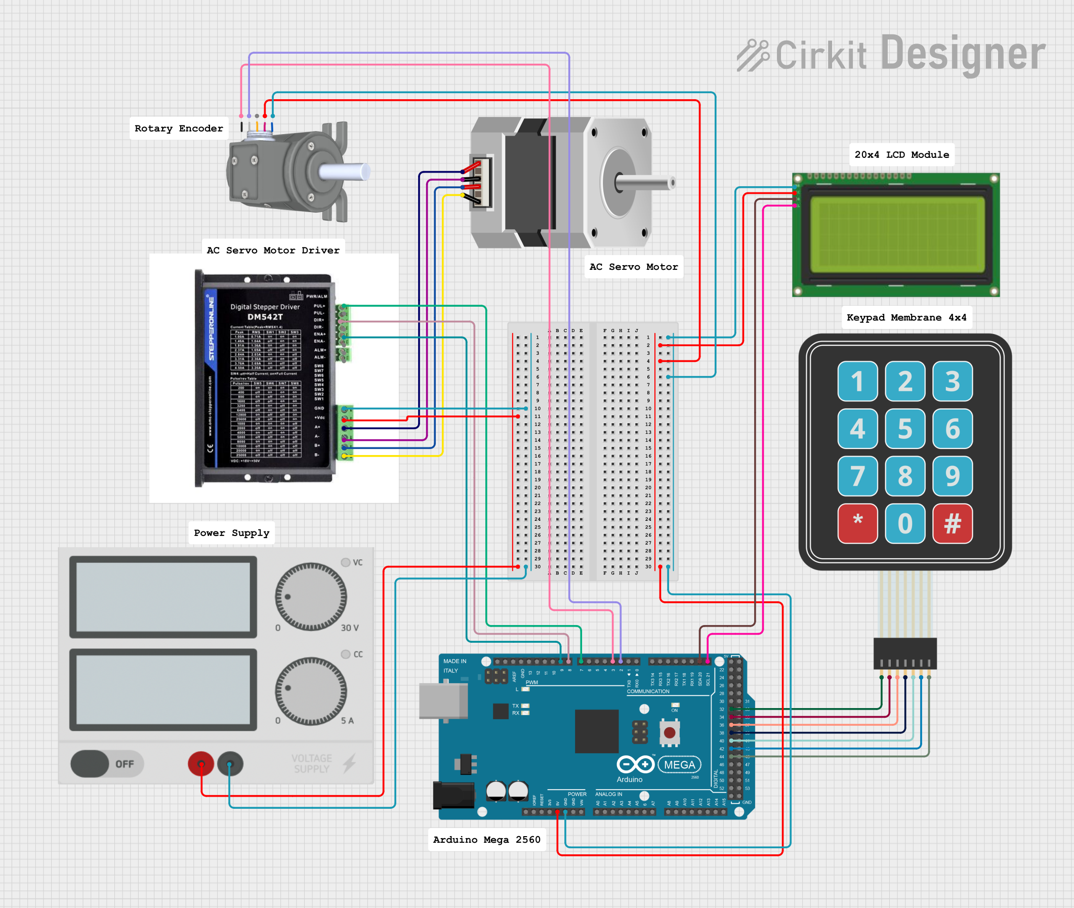
The circuit in question is designed to control a bipolar stepper motor using an Arduino Mega 2560 microcontroller and a STEPPERONLINE DM542T driver. The system also includes a rotary encoder for user input, a membrane matrix keypad for additional control options, and an LCD (20x4 with I2C interface) for displaying information. The power supply provides the necessary voltage and current to drive the stepper motor through the driver. The Arduino Mega 2560 is the central processing unit that interfaces with the input devices (keypad and rotary encoder) and controls the motor driver, which in turn drives the stepper motor. The LCD is used to display the status or feedback from the system.
Component List
Arduino Mega 2560
- Microcontroller board based on the ATmega2560
- Provides a large number of IO pins, including digital, analog, and PWM capable pins
- Features I2C communication pins used to interface with the LCD
Stepper Motor (Bipolar)
- A bipolar stepper motor with four control wires
- Controlled by the STEPPERONLINE DM542T driver
Membrane Matrix Keypad
- A simple interface for user input
- Consists of rows and columns that form a matrix of buttons
Lcd 20x4 i2c
- An alphanumeric liquid crystal display with 20 characters per line and 4 lines
- Uses I2C communication for interfacing with the Arduino Mega 2560
Power Supply
- Provides the required voltage and current to power the stepper motor and the driver
STEPPERONLINE DM542T
- A digital stepper motor driver capable of driving a bipolar stepper motor
- Accepts pulse and direction signals from the Arduino Mega 2560
Rotary Encoder incremental type side mount
- An incremental rotary encoder used for user input
- Provides feedback on rotation through two output channels
Comments
- Placeholder components for additional notes or documentation
Wiring Details
Arduino Mega 2560
GNDconnected to common ground5Vconnected to the 5V power lines of the LCD and rotary encoderD7 PWMconnected toPUL+on the STEPPERONLINE DM542TD8 PWMconnected toDIR+on the STEPPERONLINE DM542TD9 PWMconnected toENA+on the STEPPERONLINE DM542TD3 PWMconnected toAon the Rotary EncoderD2 PWMconnected toBon the Rotary EncoderD21/SCLconnected toSCLon the LCDD20/SDAconnected toSCAon the LCDD44,D42,D40,D38,D36,D34,D32connected to the corresponding columns and rows of the Membrane Matrix Keypad
Stepper Motor (Bipolar)
Dconnected toB-on the STEPPERONLINE DM542TBconnected toB+on the STEPPERONLINE DM542TCconnected toA-on the STEPPERONLINE DM542TAconnected toA+on the STEPPERONLINE DM542T
Membrane Matrix Keypad
Column 1,Column 2,Column 3connected toD40,D42,D44on the Arduino Mega 2560 respectivelyRow 1,Row 2,Row 3,Row 4connected toD32,D34,D36,D38on the Arduino Mega 2560 respectively
Lcd 20x4 i2c
GNDconnected to common ground5vconnected to the 5V power line from the Arduino Mega 2560SCAconnected toD20/SDAon the Arduino Mega 2560SCLconnected toD21/SCLon the Arduino Mega 2560
Power Supply
+connected to+Von the STEPPERONLINE DM542T-connected toGNDon the STEPPERONLINE DM542T
STEPPERONLINE DM542T
B-,B+,A-,A+connected to the corresponding wires of the Stepper Motor (Bipolar)GNDconnected to the negative terminal of the Power Supply+Vconnected to the positive terminal of the Power SupplyPUL+,DIR+,ENA+connected toD7 PWM,D8 PWM,D9 PWMon the Arduino Mega 2560 respectively
Rotary Encoder incremental type side mount
GNDconnected to common groundVCCconnected to the 5V power line from the Arduino Mega 2560Aconnected toD3 PWMon the Arduino Mega 2560Bconnected toD2 PWMon the Arduino Mega 2560
Documented Code
void setup() {
  // put your setup code here, to run once:

}

void loop() {
  // put your main code here, to run repeatedly:

}
Filename: sketch.ino
The provided code is a template for the Arduino sketch. The setup() function is called once when the sketch starts and is used to initialize the settings or pin modes. The loop() function is called repeatedly and contains the main logic of the sketch. The actual implementation details need to be filled in based on the specific requirements of the circuit's operation.