
Arduino Mega 2560 Controlled Robot with Bluetooth, GPS, Ultrasonic Sensing, and Compass Navigation
View and Edit Project In Cirkit Designer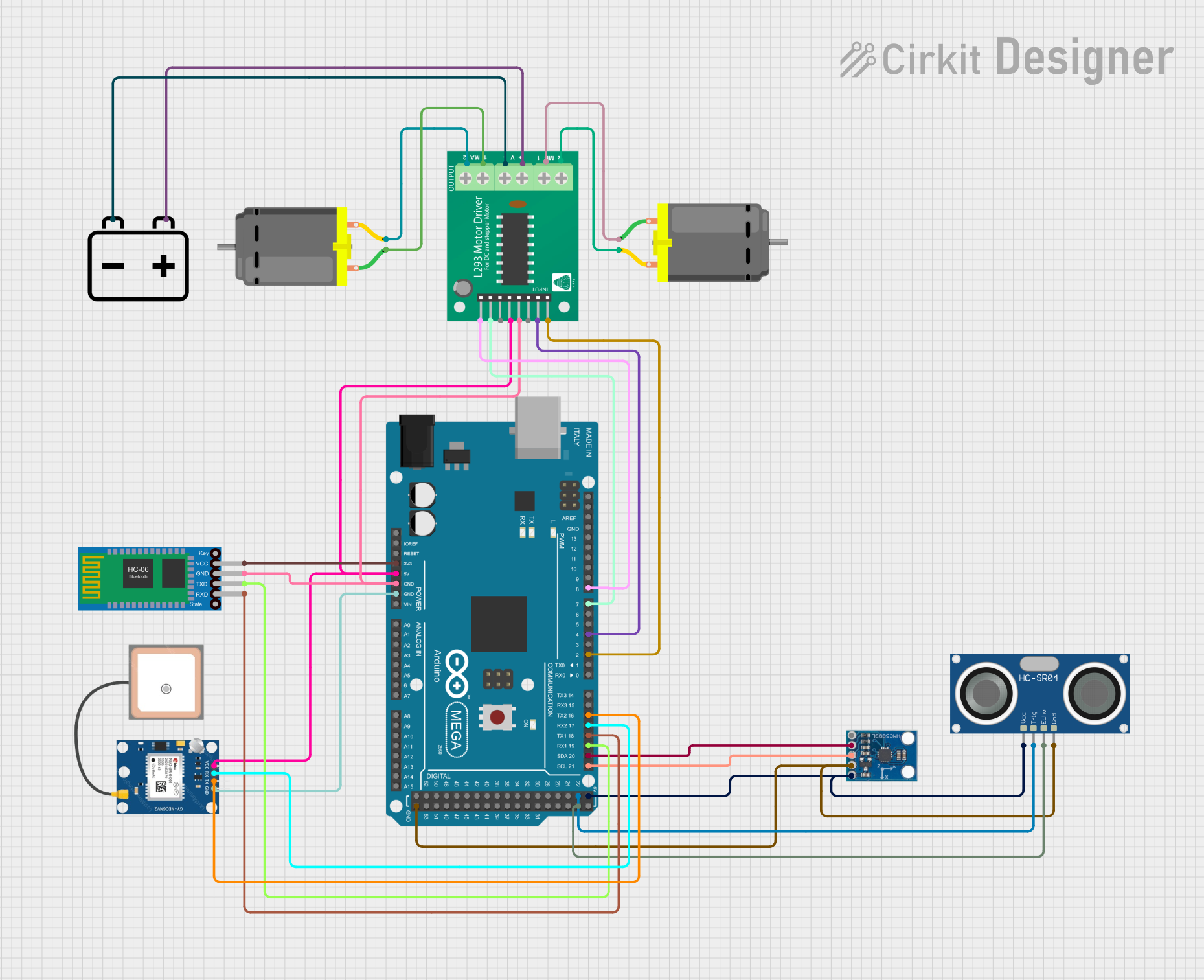
Circuit Documentation
Summary
This circuit integrates a variety of components to provide a system with Bluetooth communication, GPS functionality, motor control, and sensing capabilities. The core of the circuit is an Arduino Mega 2560, which controls a Bluetooth HC-06 module for wireless data transfer, a GPS NEO 6M module for location tracking, two DC motors via an L293D motor driver, an HC-SR04 ultrasonic sensor for distance measurement, and an HMC5883L compass module for magnetic field detection. The circuit is powered by a 12v battery, with voltage regulation provided by the Arduino for some components.
Component List
Bluetooth HC-06
- Description: A Bluetooth module for wireless communication.
- Pins: VCC, GND, TXD, RXD
GPS NEO 6M
- Description: A GPS module for obtaining geographical location data.
- Pins: VCC, RX, TX, GND
HC-SR04 Ultrasonic Sensor
- Description: An ultrasonic sensor used for measuring distances.
- Pins: VCC, TRIG, ECHO, GND
HMC5883L Compass
- Description: A digital compass module for detecting magnetic fields.
- Pins: DRDY, SDA, SCL, GND, VCC
L293D Motor Driver
- Description: A motor driver IC for controlling DC motors.
- Pins: B1, B2, A1, EN_B, EN_A, A2, GND, VCC, +, -, MPIN_1, MPIN_2, MPIN_3, MPIN_4
DC Motor
- Description: A motor for converting electrical energy into mechanical motion.
- Pins: pin 1, pin 2
Arduino Mega 2560
- Description: A microcontroller board based on the ATmega2560.
- Pins: IOREF, RESET, 3V3, 5V, GND, VIN, Digital, PWM, Analog, Communication, and Power pins
12v Battery
- Description: A power source for the circuit.
- Pins: -, +
Wiring Details
Bluetooth HC-06
- VCC connected to Arduino Mega 2560 (3V3)
- GND connected to Arduino Mega 2560 (GND)
- TXD connected to Arduino Mega 2560 (D19/RX1)
- RXD connected to Arduino Mega 2560 (D18/TX1)
GPS NEO 6M
- VCC connected to Arduino Mega 2560 (5V)
- RX connected to Arduino Mega 2560 (D17 PWM/RX2)
- TX connected to Arduino Mega 2560 (D16 PWM/TX2)
- GND connected to Arduino Mega 2560 (GND)
HC-SR04 Ultrasonic Sensor
- VCC connected to Arduino Mega 2560 (5V)
- TRIG connected to Arduino Mega 2560 (D22)
- ECHO connected to Arduino Mega 2560 (D23)
- GND connected to Arduino Mega 2560 (GND)
HMC5883L Compass
- DRDY not connected
- SDA connected to Arduino Mega 2560 (D20/SDA)
- SCL connected to Arduino Mega 2560 (D21/SCL)
- GND connected to Arduino Mega 2560 (GND)
- VCC connected to Arduino Mega 2560 (5V)
L293D Motor Driver
- B1 connected to Arduino Mega 2560 (D2 PWM)
- B2 connected to Arduino Mega 2560 (D4 PWM)
- A1 connected to Arduino Mega 2560 (D8 PWM)
- A2 connected to Arduino Mega 2560 (D7 PWM)
- GND connected to Arduino Mega 2560 (GND)
- VCC connected to Arduino Mega 2560 (5V)
-
- connected to 12v Battery (+)
-
- connected to 12v Battery (-)
- MPIN_1 connected to DC Motor (pin 2)
- MPIN_2 connected to DC Motor (pin 1)
- MPIN_3 connected to DC Motor (pin 1)
- MPIN_4 connected to DC Motor (pin 2)
DC Motors
- Motor 1 pin 1 connected to L293D Motor Driver (MPIN_2)
- Motor 1 pin 2 connected to L293D Motor Driver (MPIN_1)
- Motor 2 pin 1 connected to L293D Motor Driver (MPIN_3)
- Motor 2 pin 2 connected to L293D Motor Driver (MPIN_4)
12v Battery
-
- connected to L293D Motor Driver (+)
-
- connected to L293D Motor Driver (-)
Documented Code
Arduino Mega 2560
sketch.ino
void setup() {
  // put your setup code here, to run once:

}

void loop() {
  // put your main code here, to run repeatedly:

}
documentation.txt
(No additional documentation provided for the code)
This concludes the documentation for the given circuit. The code provided is a template and does not include any functionality. Users should implement the setup and loop functions to initialize the components and define the system's behavior.