
Arduino and ESP32-Based Smart Energy Monitoring System with Wi-Fi Connectivity
View and Edit Project In Cirkit Designer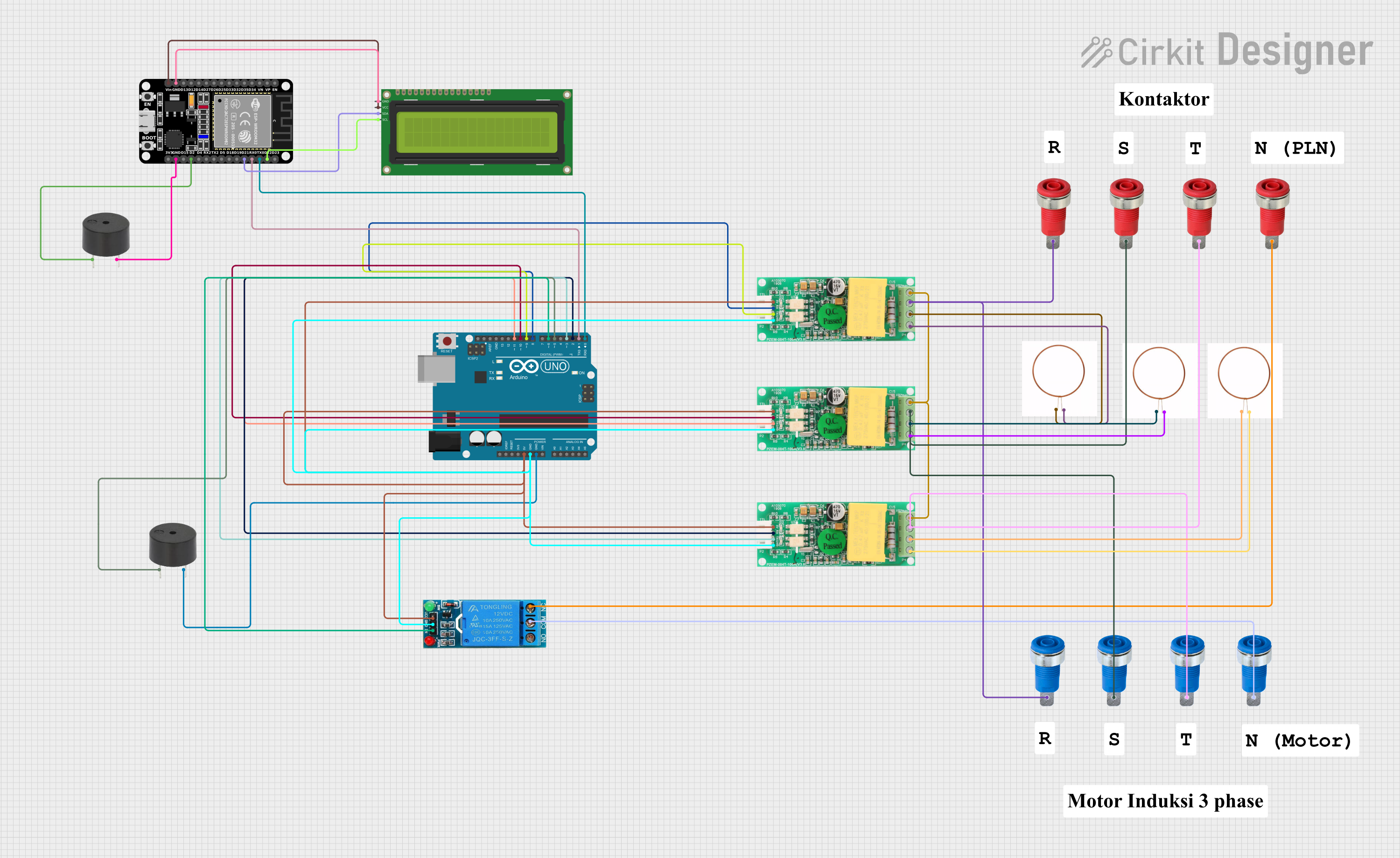
Circuit Documentation
Summary
This circuit involves an Arduino UNO, an ESP32, multiple PZEM004t energy meters, a 12V single-channel relay, a 16x2 I2C LCD, buzzers, and various panel mount banana sockets. The circuit is designed to monitor and control electrical parameters, display information on an LCD, and provide audible alerts through buzzers.
Component List
Arduino UNO
- Description: A microcontroller board based on the ATmega328P.
- Pins: UNUSED, IOREF, Reset, 3.3V, 5V, GND, Vin, A0, A1, A2, A3, A4, A5, SCL, SDA, AREF, D13, D12, D11, D10, D9, D8, D7, D6, D5, D4, D3, D2, D1, D0
ESP32 (30 pin)
- Description: A low-power system on a chip microcontroller with integrated Wi-Fi and dual-mode Bluetooth.
- Pins: EN, VP, VN, D34, D35, D32, D33, D25, D26, D27, D14, D12, D13, GND, Vin, D23, D22, TX0, RX0, D21, D19, D18, D5, TX2, RX2, D4, D2, D15, 3V3
12V SINGLE CHANNEL RELAY
- Description: A relay module that allows a microcontroller to control high voltage devices.
- Pins: NC, COM, NO, IN, GND, VCC
16x2 I2C LCD
- Description: A 16x2 character LCD display with I2C interface.
- Pins: GND, VCC, SDA, SCL
PZEM004t
- Description: A module for measuring voltage, current, power, and energy.
- Pins: VCC, RX, TX, GND, IN, OUT
Buzzer
- Description: An electronic device that emits a sound when powered.
- Pins: PIN, GND
Red Panel Mount 4mm Banana Socket
- Description: A red banana socket for panel mounting.
- Pins: Red_Pin
Blue Panel Mount 4mm Banana Socket
- Description: A blue banana socket for panel mounting.
- Pins: Blue_Pin
Copper Coil
- Description: A coil of copper wire used for inductive purposes.
- Pins: -ve, +ve
Wiring Details
Arduino UNO
- 5V: Connected to VCC of all PZEM004t modules and the 12V SINGLE CHANNEL RELAY.
- GND: Connected to GND of all PZEM004t modules, the 12V SINGLE CHANNEL RELAY, and one of the buzzers.
- D11: Connected to TX of one PZEM004t module.
- D10: Connected to RX of the same PZEM004t module.
- D9: Connected to TX of another PZEM004t module.
- D8: Connected to RX of the same PZEM004t module.
- D6: Connected to IN of the 12V SINGLE CHANNEL RELAY.
- D5: Connected to PIN of one of the buzzers.
- D3: Connected to TX of another PZEM004t module.
- D2: Connected to RX of the same PZEM004t module.
- D1: Connected to RX0 of the ESP32.
- D0: Connected to TX0 of the ESP32.
ESP32 (30 pin)
- GND: Connected to GND of the 16x2 I2C LCD and one of the buzzers.
- Vin: Connected to VCC of the 16x2 I2C LCD.
- D22: Connected to SCL of the 16x2 I2C LCD.
- D21: Connected to SDA of the 16x2 I2C LCD.
- D2: Connected to PIN of one of the buzzers.
12V SINGLE CHANNEL RELAY
- VCC: Connected to 5V of the Arduino UNO.
- GND: Connected to GND of the Arduino UNO.
- IN: Connected to D6 of the Arduino UNO.
- NC: Connected to Red_Pin of one Red Panel Mount 4mm Banana Socket.
- COM: Connected to Blue_Pin of one Blue Panel Mount 4mm Banana Socket.
16x2 I2C LCD
- GND: Connected to GND of the ESP32.
- VCC: Connected to Vin of the ESP32.
- SDA: Connected to D21 of the ESP32.
- SCL: Connected to D22 of the ESP32.
PZEM004t
- VCC: Connected to 5V of the Arduino UNO.
- GND: Connected to GND of the Arduino UNO.
- TX: Connected to D11, D9, and D3 of the Arduino UNO for different modules.
- RX: Connected to D10, D8, and D2 of the Arduino UNO for different modules.
- IN: Connected to various Red Panel Mount 4mm Banana Sockets and copper coils.
- OUT: Connected to various Blue Panel Mount 4mm Banana Sockets and copper coils.
Buzzer
- GND: One connected to GND of the Arduino UNO, another to GND of the ESP32.
- PIN: One connected to D5 of the Arduino UNO, another to D2 of the ESP32.
Red Panel Mount 4mm Banana Socket
- Red_Pin: Connected to NC of the 12V SINGLE CHANNEL RELAY and IN of various PZEM004t modules.
Blue Panel Mount 4mm Banana Socket
- Blue_Pin: Connected to COM of the 12V SINGLE CHANNEL RELAY and IN of various PZEM004t modules.
Copper Coil
- -ve: Connected to IN of various PZEM004t modules.
- +ve: Connected to OUT of various PZEM004t modules.
Documented Code
Arduino UNO Code
void setup() {
  // put your setup code here, to run once:

}

void loop() {
  // put your main code here, to run repeatedly:

}
This code is a basic template for the Arduino UNO. The setup() function is where you initialize your components, and the loop() function is where you place the code that needs to run continuously.