
ESP32-Controlled RFID Access System with Solenoid Lock and LCD Interface
View and Edit Project In Cirkit Designer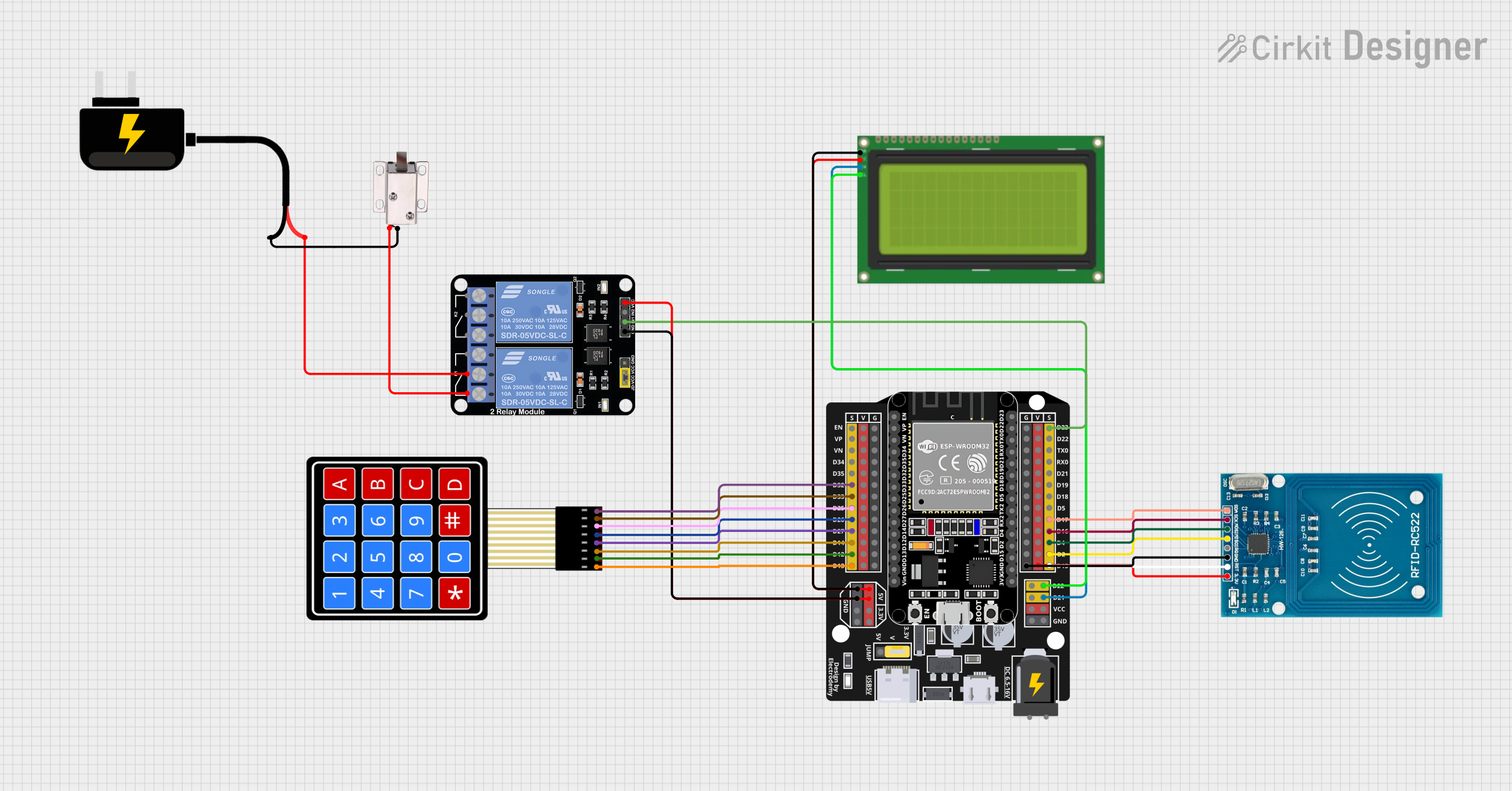
Circuit Documentation
Summary
This circuit integrates various components to perform a specific set of functions. The core of the circuit is an ESP32 Expansion Board, which interfaces with an RFID-RC522 module, a 4x4 Membrane Matrix Keypad, a 20x4 LCD with I2C interface, a 2-Channel Relay Module, and a 12V Solenoid Lock. The ESP32 Expansion Board is responsible for controlling the overall operation, including reading RFID tags, capturing keypad input, displaying information on the LCD, and controlling access through the solenoid lock via the relay module. The circuit is powered by a DC Source providing 9V.
Component List
ESP32 - Expansion Board
- Microcontroller board with WiFi and Bluetooth capabilities.
- Provides GPIO pins for interfacing with other components.
RFID-RC522
- RFID reader/writer module for contactless communication using 13.56MHz.
- Interfaces with the ESP32 for RFID tag reading.
12V Solenoid Lock
- Electromechanical lock that can be controlled via an electrical signal.
- Operates at 12V and is controlled by the relay module.
Lcd 20x4 i2c
- Alphanumeric LCD display with 20 characters per line and 4 lines.
- Uses I2C communication to display data from the ESP32.
4X4 Membrane Matrix Keypad
- Input device with 16 buttons arranged in a 4x4 matrix.
- Connected to the ESP32 for user input.
Relay Module 2 Channel
- Module with two independent relay channels.
- Controls high-power devices like the solenoid lock.
DC Source 9V
- Provides the power supply for the circuit.
Wiring Details
ESP32 - Expansion Board
D32to KeypadC4D33to KeypadC3D25to KeypadC2D26to KeypadC1D27to KeypadR4D14to KeypadR3D12to KeypadR2D13to KeypadR1D23to Relay ModuleIN1D17to RFID-RC522SDAD16to RFID-RC522SCKD4to RFID-RC522MOSID2to RFID-RC522MISOD15to RFID-RC522RSTD22to LCDSCLD21to LCDSCA5Vto LCD5vand Relay ModuleVCCGto LCDGNDand Relay ModuleGNDVto RFID-RC522VCC (3.3V)Gto RFID-RC522GND
RFID-RC522
VCC (3.3V)to ESP32VRSTto ESP32D15GNDto ESP32GIRQ(Not connected)MISOto ESP32D2MOSIto ESP32D4SCKto ESP32D16SDAto ESP32D17
12V Solenoid Lock
VCCto Relay ModuleNC1GNDto DC SourceGND
Lcd 20x4 i2c
GNDto ESP32G5vto ESP325VSCAto ESP32D21SCLto ESP32D22
4X4 Membrane Matrix Keypad
R1to ESP32D13R2to ESP32D12R3to ESP32D14R4to ESP32D27C1to ESP32D26C2to ESP32D25C3to ESP32D33C4to ESP32D32
Relay Module 2 Channel
GNDto ESP32GIN1to ESP32D23VCCto ESP325VNC1to Solenoid LockVCCCOMto DC SourceVCC
DC Source 9V
VCCto Relay ModuleCOMGNDto Solenoid LockGND
Documented Code
No code has been provided for the microcontrollers in the circuit. The code would typically include initialization routines for each of the peripherals (RFID reader, keypad, LCD, relay module), as well as the main application logic to handle user input, RFID tag reading, and control of the solenoid lock. It would also manage the display output on the LCD screen.