
Arduino-Controlled Manufacturing Station with Display Feedback
View and Edit Project In Cirkit Designer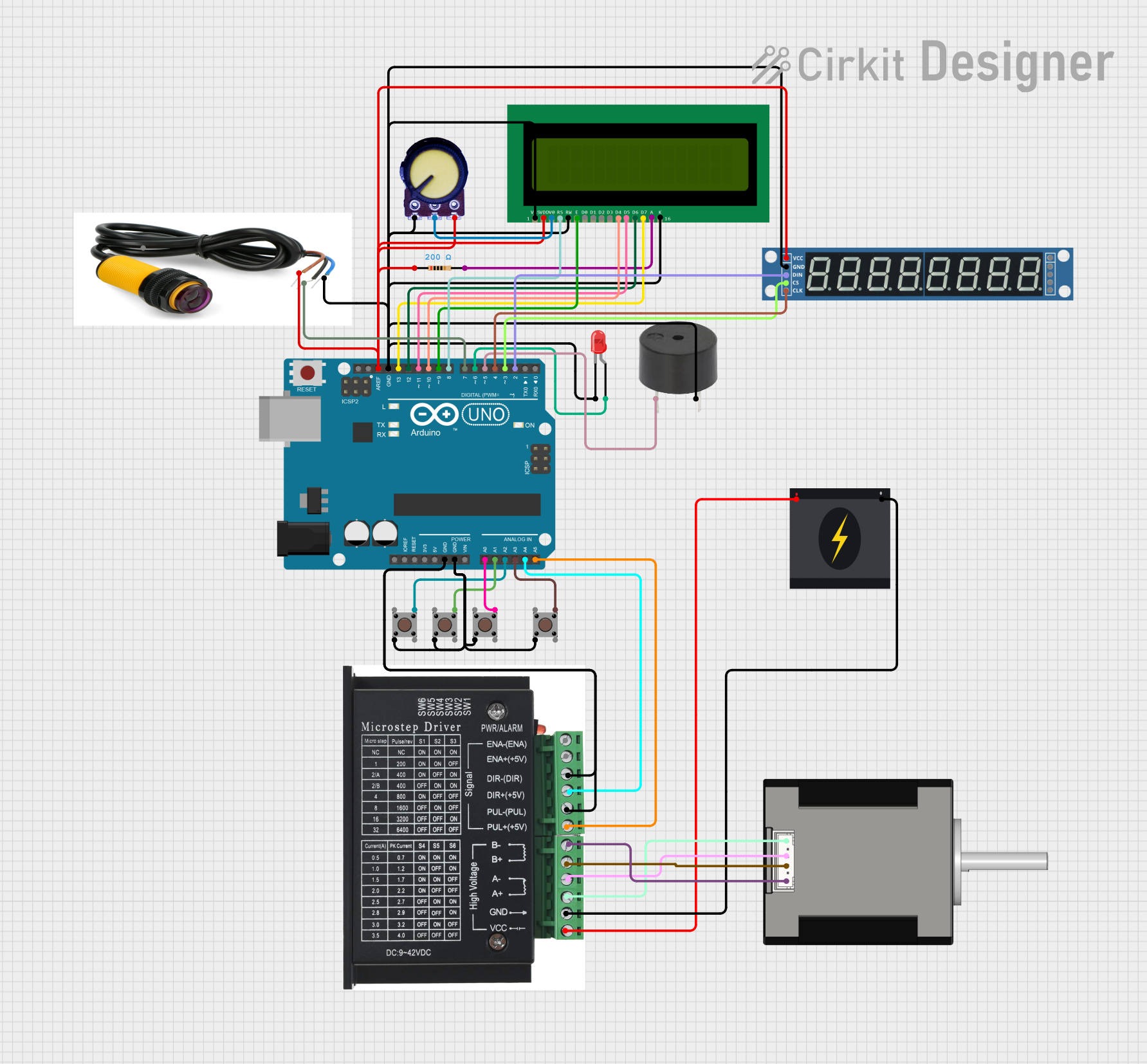
Circuit Documentation
Summary
This document provides a detailed overview of a circuit that includes a variety of components such as a 16X2 LCD, Arduino UNO, resistors, potentiometers, pushbuttons, a MAX7219 8-digit 7-segment display driver, LEDs, a buzzer, a stepper driver, a Nema 17 stepper motor, an E18-D80NK infrared proximity sensor, and a 240v power source. The circuit is designed to interface with various input and output devices, controlled by an Arduino UNO microcontroller. The Arduino UNO is programmed to interact with these components, although the specific functionality is not detailed in the provided code.
Component List
16X2 LCD
A liquid crystal display that can show 16 characters per line with 2 lines. It has a variety of control and data pins for interfacing with a microcontroller.
Arduino UNO
A microcontroller board based on the ATmega328P. It has digital input/output pins, analog inputs, a USB connection for programming, and power management features.
Resistor (200 Ohms)
A passive two-terminal electrical component that implements electrical resistance as a circuit element.
Potentiometer
A three-terminal resistor with a sliding or rotating contact that forms an adjustable voltage divider.
Pushbutton (x4)
A simple switch mechanism for controlling some aspect of a machine or a process. Buttons are typically made out of hard material, usually plastic or metal.
MAX7219 8 Digit 7 Segment
An integrated circuit that is designed to control 8-digit 7-segment numeric LED displays. It simplifies the process of controlling multiple LEDs in a matrix or display.
LED: Two Pin (red)
A basic red light-emitting diode with two pins, an anode, and a cathode, used for indication and illumination.
Buzzer
An audio signaling device that may be mechanical, electromechanical, or piezoelectric.
STEPPER DRIVER
A driver module that controls the operation of a stepper motor, providing the necessary current to the motor in a controlled manner.
Nema 17 42-STH48
A stepper motor that is commonly used in 3D printers, CNC machines, and other precision motion control applications.
E18-D80NK
An infrared proximity sensor used for object detection.
240v Power Source
A power source that provides 240 volts of alternating current (AC).
Wiring Details
16X2 LCD
- VSS, K, RW connected to GND
- VDD connected to 5V through a 200 Ohm resistor
- V0 connected to the wiper of the potentiometer for contrast adjustment
- RS connected to Arduino UNO D8
- E connected to Arduino UNO D9
- D4 connected to Arduino UNO D10
- D6 connected to Arduino UNO D12
- D5 connected to Arduino UNO D11
- D7 connected to Arduino UNO D13
- A connected to 5V through a 200 Ohm resistor for backlight
Arduino UNO
- GND connected to various components as common ground
- AREF connected to 5V
- A0-A5 connected to pushbuttons and stepper driver control inputs
- D2-D13 connected to LCD, MAX7219, LEDs, buzzer, and E18-D80NK sensor
Resistor (200 Ohms)
- One pin connected to 16X2 LCD A for backlight control
- One pin connected to 5V
Potentiometer
- GND connected to ground
- Output connected to 16X2 LCD V0 for contrast control
- VCC connected to 5V
Pushbuttons (x4)
- Pin 2 (in) connected to GND
- Pin 3 (out) connected to Arduino UNO A0-A3
MAX7219 8 Digit 7 Segment
- GND connected to ground
- VCC connected to 5V
- DIN connected to Arduino UNO D2
- CS connected to Arduino UNO D3
- CLK connected to Arduino UNO D4
LED: Two Pin (red)
- Cathode connected to GND
- Anode connected to Arduino UNO D6
Buzzer
- GND connected to ground
- PIN connected to Arduino UNO D5
STEPPER DRIVER
- ENA-, DIR-, PUL- connected to GND
- DIR+ connected to Arduino UNO A4
- PUL+ connected to Arduino UNO A5
- B-, A- connected to Nema 17 stepper motor
- B+, A+ connected to Nema 17 stepper motor
- GND connected to 240v Power Source Neutral
- VCC connected to 240v Power Source Live
Nema 17 42-STH48
- A2 (black), B1 (Blue) connected to STEPPER DRIVER A-
- A1 (Green), B2 (Red) connected to STEPPER DRIVER A+
E18-D80NK
- GND connected to ground
- VCC connected to 5V
- DATA connected to Arduino UNO D7
240v Power Source
- Live connected to STEPPER DRIVER VCC
- Neutral connected to STEPPER DRIVER GND
Documented Code
void setup() {
  // put your setup code here, to run once:

}

void loop() {
  // put your main code here, to run repeatedly:

}
The provided code is a template with empty setup() and loop() functions, which are the standard structure for Arduino sketches. The setup() function is intended to contain initialization code that runs once when the microcontroller is powered on or reset. The loop() function is intended to contain the main logic of the sketch, which runs repeatedly as long as the microcontroller is powered. Additional code would be required to implement the specific functionality of the circuit.