Cirkit Designer
Your all-in-one circuit design IDE
Home /
Project Documentation
Arduino-Controlled DC Motor with Pushbutton Activation and Relay Switching

Circuit Documentation
Summary
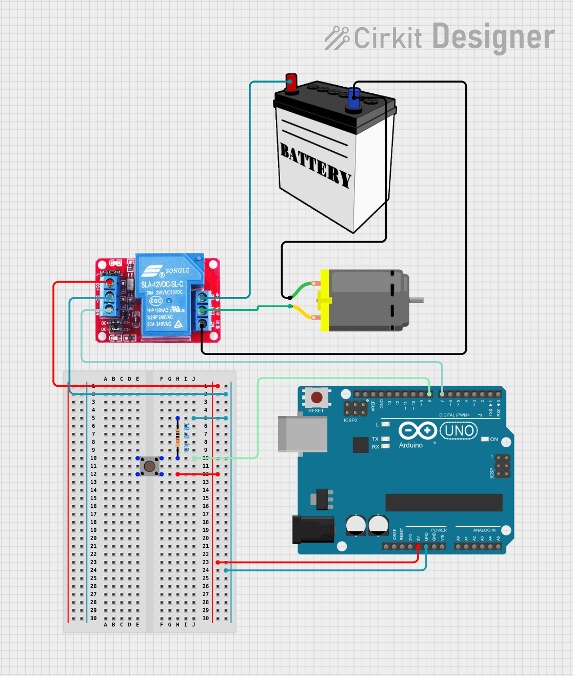
The circuit in question is designed to control a DC motor using an Arduino UNO microcontroller, with the motor's power being switched by a 12V relay. The relay is actuated by a pushbutton through the Arduino, which allows for manual control of the motor. A resistor is included in the circuit for current limiting purposes. The power is supplied by a 12V battery.
Component List
Pushbutton
- Description: A simple pushbutton used to trigger an action in the circuit.
- Pins:
- Pin 3 (out)
- Pin 4 (out)
- Pin 1 (in)
- Pin 2 (in)
Arduino UNO
- Description: A microcontroller board based on the ATmega328P, widely used for building digital devices and interactive objects that can sense and control objects in the physical world.
- Pins: UNUSED, IOREF, Reset, 3.3V, 5V, GND, Vin, A0 to A5, SCL, SDA, AREF, D13 to D0
12V Battery
- Description: A power source for the circuit, providing a voltage of 12V.
- Pins:
- VCC
- GND
12V Relay
- Description: An electromechanical switch that allows a low-power circuit to switch a relatively high current or voltage on and off.
- Pins:
- NO (Normally Open)
- COM (Common)
- NC (Normally Closed)
- DC+ (Power Supply Positive)
- DC- (Power Supply Negative)
- IN (Input Signal)
DC Motor
- Description: An electric motor that runs on direct current (DC) electricity.
- Pins:
- Pin 1
- Pin 2
Resistor
- Description: A passive two-terminal electrical component that implements electrical resistance as a circuit element.
- Pins:
- Pin 1
- Pin 2
- Properties:
- Resistance: 10000 Ohms
Wiring Details
Pushbutton
- Pin 3 (out) connected to 12V Relay DC+
- Pin 1 (in) connected to Resistor pin2 and Arduino UNO D8
Arduino UNO
- 5V connected to Pushbutton Pin 3 (out) and 12V Relay DC+
- GND connected to Resistor pin1 and 12V Relay DC-
- D8 connected to Pushbutton Pin 1 (in) and Resistor pin2
- D7 connected to 12V Relay IN
12V Battery
- VCC connected to 12V Relay NO
- GND connected to DC Motor pin 1 and 12V Relay NC
12V Relay
- DC+ connected to Pushbutton Pin 3 (out) and Arduino UNO 5V
- DC- connected to Resistor pin1 and Arduino UNO GND
- IN connected to Arduino UNO D7
- NO connected to 12V Battery VCC
- COM connected to DC Motor pin 2
- NC connected to DC Motor pin 1 and 12V Battery GND
DC Motor
- Pin 1 connected to 12V Relay NC and 12V Battery GND
- Pin 2 connected to 12V Relay COM
Resistor
- Pin 1 connected to 12V Relay DC- and Arduino UNO GND
- Pin 2 connected to Pushbutton Pin 1 (in) and Arduino UNO D8
Documented Code
sketch.ino
void setup() {
  // put your setup code here, to run once:

}

void loop() {
  // put your main code here, to run repeatedly:

}
documentation.txt
(No additional documentation provided)
This concludes the documentation for the provided circuit. The code provided is a template and does not contain any functional logic to control the circuit. Additional code would be required to read the pushbutton state and control the relay to turn the DC motor on and off.