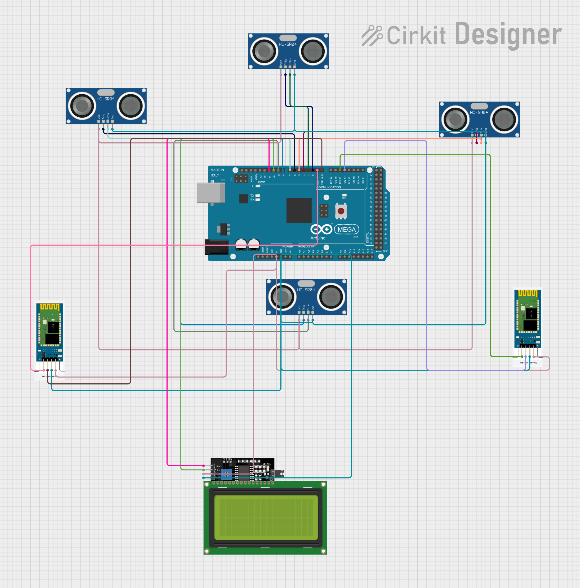
Arduino Mega 2560 Controlled Ultrasonic Sensor Array with I2C LCD Display and Bluetooth Interface

Circuit Documentation
Summary
This circuit integrates an Arduino Mega 2560 microcontroller with multiple peripherals including HC-SR04 ultrasonic sensors, an LCD Display 20x4 with I2C interface, and HC-06 Bluetooth modules. The Arduino Mega 2560 serves as the central processing unit, interfacing with the ultrasonic sensors for distance measurement, displaying data on the LCD, and communicating via Bluetooth using the HC-06 modules. The circuit is designed to be powered by the Arduino's 5V output, with common ground connections throughout.
Component List
Arduino Mega 2560
- Microcontroller board based on the ATmega2560
- Offers 54 digital input/output pins, 16 analog inputs, 4 UARTs, a 16 MHz crystal oscillator, a USB connection, a power jack, an ICSP header, and a reset button.
HC-SR04 Ultrasonic Sensor
- Ultrasonic distance measuring module
- Features VCC, TRIG, ECHO, and GND pins
- Operates by sending an ultrasonic pulse and measuring the time taken for the echo to return.
LCD Display 20x4 I2C
- Alphanumeric liquid crystal display with 20 characters per line and 4 lines
- I2C interface for communication, reducing the number of pins needed for operation
- Has SCL, SDA, VCC, and GND pins.
HC-06 Bluetooth Module
- Bluetooth serial communication module
- Can be used for wireless data exchange with a Bluetooth-enabled device
- Features RXD, TXD, GND, and VCC pins.
Wiring Details
Arduino Mega 2560
- 5V connected to VCC of all HC-SR04 sensors, both HC-06 modules, and the LCD Display
- GND connected to GND of all HC-SR04 sensors, both HC-06 modules, and the LCD Display
- D17 PWM/RX2 connected to TXD of one HC-06 module
- D16 PWM/TX2 connected to RXD of one HC-06 module
- D0 RX0 connected to TXD of the other HC-06 module
- D1 TX0 connected to RXD of the other HC-06 module
- D2 PWM connected to TRIG of one HC-SR04 sensor
- D3 PWM connected to ECHO of one HC-SR04 sensor
- D4 PWM connected to TRIG of another HC-SR04 sensor
- D5 PWM connected to ECHO of another HC-SR04 sensor
- D6 PWM connected to TRIG of another HC-SR04 sensor
- D7 PWM connected to ECHO of another HC-SR04 sensor
- D8 PWM connected to TRIG of another HC-SR04 sensor
- D9 PWM connected to ECHO of another HC-SR04 sensor
- D10 PWM connected to SDA of the LCD Display
- D11 PWM connected to SCL of the LCD Display
HC-SR04 Ultrasonic Sensors
- VCC connected to 5V from the Arduino
- GND connected to GND on the Arduino
- TRIG and ECHO pins connected to specified digital pins on the Arduino for triggering and receiving the ultrasonic pulses.
LCD Display 20x4 I2C
- VCC connected to 5V from the Arduino
- GND connected to GND on the Arduino
- SDA and SCL connected to the I2C pins on the Arduino.
HC-06 Bluetooth Modules
- VCC connected to 5V from the Arduino
- GND connected to GND on the Arduino
- TXD and RXD connected to specified UART pins on the Arduino for serial communication.
Documented Code
Arduino Mega 2560 Code (sketch.ino)
void setup() {
  // put your setup code here, to run once:

}

void loop() {
  // put your main code here, to run repeatedly:

}
This code template provides the basic structure for an Arduino sketch with setup() and loop() functions. The setup() function is intended for initialization code that runs once, such as setting pin modes or starting libraries. The loop() function contains the main logic of the program, which runs continuously after setup() completes.
The actual implementation details would depend on the specific requirements of the circuit's functionality, such as reading sensor data, processing it, and communicating via Bluetooth or displaying information on the LCD.