
Raspberry Pi 3B-Based Multi-Sensor Monitoring System with I2C Communication and Servo Control
View and Edit Project In Cirkit Designer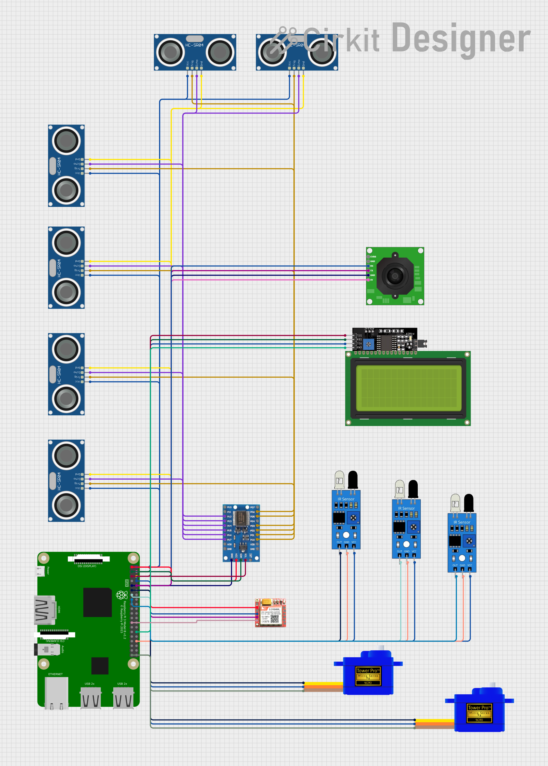
Circuit Documentation
Summary
This circuit integrates a Raspberry Pi 3B as the central processing unit, interfacing with multiple sensors and peripherals to perform various tasks. The circuit includes ultrasonic sensors (HC-SR04) for distance measurement, infrared sensors for object detection, servomotors (SG90) for movement, an I2C LCD display for user interface, a TTL Serial JPEG Camera for image capture, a SIM800L module for cellular communication, and an IO expander to increase the number of GPIOs available on the Raspberry Pi. The circuit is powered by the Raspberry Pi's 3.3V and 5V pins, with ground connections distributed across the components.
Component List
Raspberry Pi 3B
- A single-board computer with multiple GPIO pins used for interfacing with various sensors and modules.
HC-SR04 Ultrasonic Sensor
- Ultrasonic distance measuring module that provides 2cm to 400cm non-contact measurement functionality.
TTL Serial JPEG Camera
- A camera module that captures JPEG images and sends them over a serial connection.
IO Expander
- A device that expands the number of IO pins available from the Raspberry Pi, interfacing via I2C.
IR Sensor
- An infrared sensor used for object detection.
Servomotor SG90
- A small and lightweight servo that is used for precise control of mechanical movement.
LCD Display 20x4 I2C
- An alphanumeric liquid crystal display that allows for the display of text on 4 lines of 20 characters each, interfaced via I2C.
SIM800L
- A GSM/GPRS module that allows for cellular communication including SMS and data.
Wiring Details
Raspberry Pi 3B
3v3connected to IO expander VCC and SIM800L VCCGPIO2(SDA) connected to IO expander SDA and LCD Display SDAGPIO3(SCL) connected to IO expander SCL and LCD Display SCLGNDconnected to IO expander GND, TTL Serial JPEG Camera GND, SIM800L GND, Servomotors GND, IR sensors GND, and HC-SR04 sensors GNDGPIO17connected to Servomotors SIG and IR sensor outGPIO27connected to IR sensor outGPIO22connected to IR sensor outGPIO15(RX) connected to TTL Serial JPEG Camera TX and SIM800L RXDGPIO14(TX) connected to TTL Serial JPEG Camera RX and SIM800L TXD5Vconnected to TTL Serial JPEG Camera 5V, Servomotors VCC, IR sensors VCC, and HC-SR04 sensors VCC
HC-SR04 Ultrasonic Sensor
VCCconnected to Raspberry Pi 5VGNDconnected to Raspberry Pi GNDTRIGandECHOpins connected to various IO expander pins
TTL Serial JPEG Camera
GNDconnected to Raspberry Pi GNDRXconnected to Raspberry Pi GPIO15TXconnected to Raspberry Pi GPIO145Vconnected to Raspberry Pi 5V
IO Expander
VCCconnected to Raspberry Pi 3v3GNDconnected to Raspberry Pi GNDSDAconnected to Raspberry Pi GPIO2SCLconnected to Raspberry Pi GPIO3P01,P03,P05,P06,P00,P02connected to HC-SR04 TRIG pinsP16,P14,P13,P12,P17,P15connected to HC-SR04 ECHO pins
IR Sensor
outconnected to Raspberry Pi GPIO17, GPIO27, GPIO22gndconnected to Raspberry Pi GNDvccconnected to Raspberry Pi 5V
Servomotor SG90
SIGconnected to Raspberry Pi GPIO17VCCconnected to Raspberry Pi 5VGNDconnected to Raspberry Pi GND
LCD Display 20x4 I2C
SCLconnected to Raspberry Pi GPIO3SDAconnected to Raspberry Pi GPIO2VCCconnected to Raspberry Pi 5VGNDconnected to Raspberry Pi GND
SIM800L
VCCconnected to Raspberry Pi 3v3GNDconnected to Raspberry Pi GNDRXDconnected to Raspberry Pi GPIO14TXDconnected to Raspberry Pi GPIO15
Documented Code
No code was provided for the microcontrollers in the circuit. The documentation of the code would typically include descriptions of the functionality implemented, setup and loop functions, and any libraries used for interfacing with the hardware components. It would also include comments within the code to explain the purpose of each section and the logic behind it.