
Arduino UNO-Based Accident Detection and Alert System with GPS and GSM
View and Edit Project In Cirkit Designer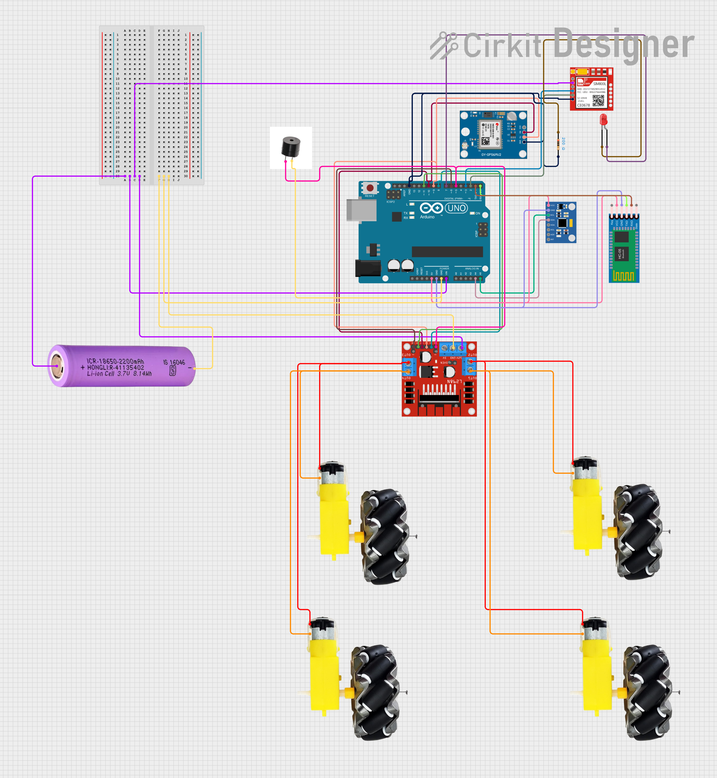
Circuit Documentation
Summary
This document provides a detailed overview of a circuit designed to detect impacts and send alerts via SMS using a SIM800L module. The circuit includes various components such as an Arduino UNO, GPS module, Bluetooth module, accelerometer, motor driver, and more. The Arduino UNO serves as the central microcontroller, interfacing with all other components to perform the required tasks.
Component List
Neo 6M GPS Module
- Pins: GND, TX, RX, VCC
- Description: GPS module used for obtaining location data.
- Purpose: Provides GPS coordinates for alert messages.
Sim800l
- Pins: NET, RST, VCC, RXD, TXD, GND
- Description: GSM module used for sending SMS and making calls.
- Purpose: Sends alert messages and makes emergency calls.
Buzzer
- Pins: +, GND
- Description: Audio alert device.
- Purpose: Provides an audible alert when an impact is detected.
Motor and Wheels
- Pins: vcc, GND
- Description: Motor and wheel assembly.
- Purpose: Provides mobility to the system.
Arduino UNO
- Pins: UNUSED, IOREF, Reset, 3.3V, 5V, GND, Vin, A0, A1, A2, A3, A4, A5, SCL, SDA, AREF, D13, D12, D11, D10, D9, D8, D7, D6, D5, D4, D3, D2, D1, D0
- Description: Microcontroller board.
- Purpose: Central control unit for the circuit.
LED: Two Pin (red)
- Pins: cathode, anode
- Description: Red LED.
- Purpose: Visual indicator.
Resistor
- Pins: pin1, pin2
- Description: 200 Ohms resistor.
- Purpose: Current limiting for the LED.
MPU6050 Accelerometer + Gyroscope (Wokwi Compatible)
- Pins: INT, AD0, XCL, XDA, SDA, SCL, GND, VCC
- Description: Accelerometer and gyroscope module.
- Purpose: Detects impacts and measures orientation.
L298N DC Motor Driver
- Pins: OUT1, OUT2, 12V, GND, 5V, OUT3, OUT4, 5V-ENA-JMP-I, 5V-ENA-JMP-O, +5V-J1, +5V-J2, ENA, IN1, IN2, IN3, IN4, ENB
- Description: Dual H-Bridge motor driver.
- Purpose: Controls the motors.
HC-05 Bluetooth Module
- Pins: Key, VCC, TXD, RXD, State, GND
- Description: Bluetooth module.
- Purpose: Wireless communication.
Battery 18650
- Pins: +, -
- Description: Rechargeable lithium-ion battery.
- Purpose: Power supply for the circuit.
Wiring Details
Neo 6M GPS Module
- GND connected to Arduino UNO GND
- TX connected to Arduino UNO D9
- RX connected to Arduino UNO D10
- VCC connected to Arduino UNO 5V
Sim800l
- NET not connected
- RST not connected
- VCC connected to Battery 18650 +
- RXD connected to Arduino UNO D3
- TXD connected to Arduino UNO D2
- GND connected to Arduino UNO GND
Buzzer
- + connected to Arduino UNO D5
- GND connected to Arduino UNO GND
Motor and Wheels
- vcc connected to L298N DC motor driver OUT2
- GND connected to L298N DC motor driver OUT1
Arduino UNO
- Vin connected to Battery 18650 +
- GND connected to Battery 18650 -
- 5V connected to MPU6050 Accelerometer + Gyroscope VCC
- A4 connected to MPU6050 Accelerometer + Gyroscope SDA
- A5 connected to MPU6050 Accelerometer + Gyroscope SCL
- D11 connected to L298N DC motor driver IN4
- D10 connected to Neo 6M GPS Module RX
- D9 connected to Neo 6M GPS Module TX
- D8 connected to L298N DC motor driver IN1
- D7 connected to LED: Two Pin (red) anode
- D6 connected to L298N DC motor driver ENB
- D5 connected to L298N DC motor driver ENA
- D3 connected to Sim800l RXD
- D2 connected to Sim800l TXD
- D1 connected to HC-05 Bluetooth Module RXD
- D0 connected to HC-05 Bluetooth Module TXD
LED: Two Pin (red)
- cathode connected to Resistor pin1
- anode connected to Arduino UNO D7
Resistor
- pin1 connected to LED: Two Pin (red) cathode
- pin2 connected to Arduino UNO GND
MPU6050 Accelerometer + Gyroscope (Wokwi Compatible)
- VCC connected to Arduino UNO 5V
- GND connected to Arduino UNO GND
- SDA connected to Arduino UNO A4
- SCL connected to Arduino UNO A5
L298N DC Motor Driver
- 12V connected to Battery 18650 +
- GND connected to Battery 18650 -
- IN1 connected to Arduino UNO D8
- IN2 connected to Neo 6M GPS Module TX
- IN3 connected to Neo 6M GPS Module RX
- IN4 connected to Arduino UNO D11
- ENA connected to Arduino UNO D5
- ENB connected to Arduino UNO D6
- OUT1 connected to Motor and Wheels GND
- OUT2 connected to Motor and Wheels vcc
- OUT3 connected to Motor and Wheels vcc
- OUT4 connected to Motor and Wheels GND
HC-05 Bluetooth Module
- VCC connected to MPU6050 Accelerometer + Gyroscope VCC
- GND connected to MPU6050 Accelerometer + Gyroscope GND
- TXD connected to Arduino UNO D0
- RXD connected to Arduino UNO D1
Battery 18650
- + connected to Arduino UNO Vin
- - connected to Arduino UNO GND
Documented Code
#include <AltSoftSerial.h>
#include <TinyGPS++.h>
#include <Wire.h>
#include <math.h>
#include <SoftwareSerial.h>

const String EMERGENCY_PHONE = "+91xxxxxxxxxx";
#define rxPin 2
#define txPin 3

SoftwareSerial sim800(rxPin, txPin);
AltSoftSerial neogps;
TinyGPSPlus gps;

// RX Pin To D9
// TX Pin To D8

String sms_status, sender_number, received_date, msg;
String latitude, longitude;
#define BUZZER 5
#define BUTTON 6
#define xPin A0
#define yPin A1
#define zPin A2

byte updateflag;

int xaxis = 0, yaxis = 0, zaxis = 0;
int deltx = 0, delty = 0, deltz = 0;
int vibration = 2;
int devibrate = 75;
int magnitude = 0;
int sensitivity = 20;

double angle;
boolean impact_detected = false;
unsigned long time1;
unsigned long impact_time;
unsigned long alert_delay = 30000;

void setup()
{
  Serial.begin(9600);
  sim800.begin(9600);
  neogps.begin(9600);
  pinMode(BUZZER, OUTPUT);
  pinMode(BUTTON, INPUT_PULLUP);

  sms_status = "";
  sender_number = "";
  received_date = "";
  msg = "";
  sim800.println("AT");
  delay(1000);
  sim800.println("ATE1");
  delay(1000);
  sim800.println("AT+CPIN?");
  delay(1000);
  sim800.println("AT+CMGF=1");
  delay(1000);
  sim800.println("AT+CNMI=1,1,0,0,0");
  delay(1000);
  time1 = micros();
  xaxis = analogRead(xPin);
  yaxis = analogRead(yPin);
  zaxis = analogRead(zPin);
}

void loop()
{
  if (micros() - time1 > 4999) Impact();