Cirkit Designer
Your all-in-one circuit design IDE
Home /
Project Documentation
Arduino UNO Based Environmental Control System with SHT31 Sensor and Relay-Controlled Fan

Circuit Documentation
Summary
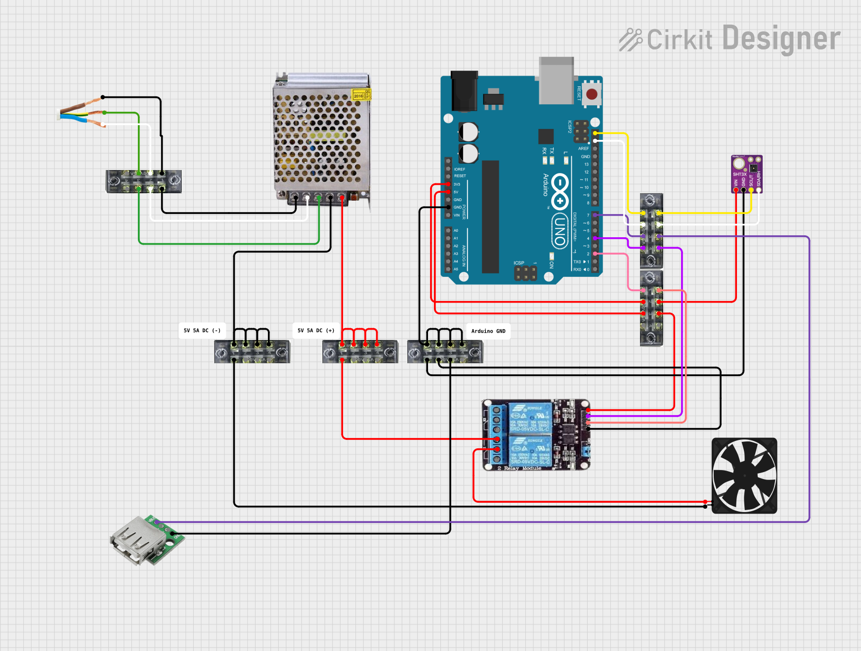
This document provides a detailed overview of a circuit that includes an Arduino UNO as the central microcontroller, interfaced with various components such as a 2-channel relay, an SHT31 temperature and humidity sensor, a fan, a USB female connector, and a power supply. The circuit is designed to control the fan and gather environmental data while being powered through a 5V power supply. The Arduino UNO facilitates the control logic and sensor data processing.
Component List
Arduino UNO
- Microcontroller board based on the ATmega328P
- It has 14 digital input/output pins, 6 analog inputs, a 16 MHz quartz crystal, a USB connection, a power jack, an ICSP header, and a reset button.
2-Channel Relay
- An electrically operated switch that allows you to control two circuits with a single signal.
- It has normally closed (NC), common (COM), and normally open (NO) terminals for each channel, as well as inputs for the control signal (IN1, IN2) and power (VCC, GND).
SHT31
- A digital temperature and humidity sensor that provides calibrated, linearized signals in digital, I2C format.
- It has four pins: VCC, GND, SDA, and SCL.
Fan
- An electric fan powered by 5V.
- It has two pins: GND and 5V.
Power Supply 5V 5A
- A power supply unit that provides 5V DC at up to 5A current.
- It has inputs for 220V AC (positive and negative poles) and outputs for GND and 12V-24V DC.
AC Wire
- A wire used to connect the power supply to the AC mains.
- It has three wires: Line, Earth, and Neutral.
USB Female
- A female USB connector that can be used to provide power or data connections.
- It has four pins: VCC, GND, -D, and +D.
Terminal Blocks (04-01)
- Connector blocks used for making multiple wire connections.
- Each block has eight numbered pins.
Comments
- Non-electrical components used for adding notes or labels within the circuit design.
Wiring Details
Arduino UNO
3.3Vconnected to terminal block5Vconnected to terminal blockGNDconnected to multiple terminal blocksSCLconnected to terminal block for I2C communicationSDAconnected to terminal block for I2C communicationD7connected to terminal block for digital controlD4connected to terminal block for digital controlD2connected to terminal block for digital control
2-Channel Relay
NCnot connectedCOMconnected to the fanNOconnected to terminal blockVCCconnected to terminal block for powerIN2connected to terminal block for control signalIN1connected to terminal block for control signalGNDconnected to terminal block for ground
SHT31
VCCconnected to terminal block for powerGNDconnected to terminal block for groundSDAconnected to terminal block for I2C communicationSCLconnected to terminal block for I2C communication
Fan
5Vconnected to the relay's COM terminalGNDconnected to terminal block for ground
Power Supply 5V 5A
220V Positive Pole (AC)connected to AC wire220V Negative Pole (AC)connected to AC wireGNDconnected to multiple terminal blocks for groundGND (DC)connected to terminal blocks for ground12V-24V Output (DC)connected to terminal blocks for power distribution
AC Wire
Lineconnected to power supplyEarthconnected to terminal block for safetyNeutralconnected to power supply
USB Female
VCCconnected to terminal block for powerGNDconnected to terminal block for ground-Dnot connected+Dnot connected
Terminal Blocks (04-01)
- Used for distributing power, ground, and signals throughout the circuit.
Documented Code
Arduino UNO Code (sketch.ino)
void setup() {
  // put your setup code here, to run once:

}

void loop() {
  // put your main code here, to run repeatedly:

}
Additional Notes
- The code provided for the Arduino UNO is a template with empty
setup()andloop()functions. The actual logic for controlling the relay and reading data from the SHT31 sensor needs to be implemented within these functions. - The
documentation.txtfile is empty and can be used to add further explanations or instructions related to the code.