Cirkit Designer
Your all-in-one circuit design IDE
Home /
Project Documentation
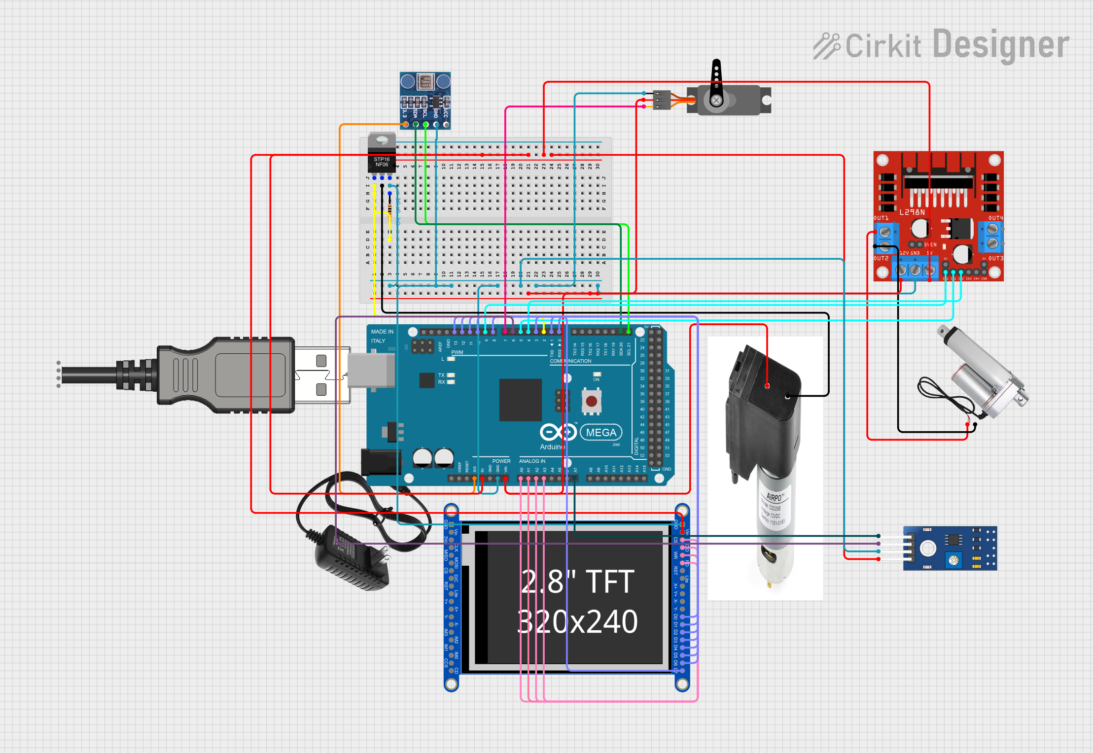
Arduino Mega 2560-Based Automated Vacuum Pump and Linear Actuator Control System with TFT Display

Circuit Documentation
Summary
This document provides a detailed overview of a circuit that includes various components such as a vacuum pump, MOSFET, resistors, sensors, a TFT display, and an Arduino Mega 2560 microcontroller. The circuit is designed to control and monitor various devices and sensors, with the Arduino Mega 2560 serving as the central control unit.
Component List
Vacuum Pump - 12V
- Description: A 12V vacuum pump.
- Pins: Power/IN, GND / OUT
STP16NF06 N-Channel Power MOSFET
- Description: An N-Channel Power MOSFET used for switching and amplification.
- Pins: gate, drain, source
Resistor
- Description: A 10k Ohm resistor.
- Pins: pin1, pin2
- Properties:
- Resistance: 10000 Ohms
USB Plug
- Description: A USB plug for power and data connections.
- Pins: GND, D+, D-, 5V+, Out
12V Power Supply
- Description: A 12V power supply.
- Pins: +, -
BMP180
- Description: A barometric pressure sensor.
- Pins: 3.3, SDA, SCL, GND, VCC
Linear Actuator
- Description: A linear actuator.
- Pins: +, -
L298N DC Motor Driver
- Description: A DC motor driver.
- Pins: OUT1, OUT2, 12V, GND, 5V, OUT3, OUT4, 5V-ENA-JMP-I, 5V-ENA-JMP-O, +5V-J1, +5V-J2, ENA, IN1, IN2, IN3, IN4, ENB
Adafruit 2.8inch Resistive TFT
- Description: A 2.8-inch resistive TFT display.
- Pins: GND, VIN, +3.3V, LCD_CS, LCD_CD_SCK, MISO, LCD_WR_DC, MOSI, LCD_RD, LCD_RST, LCD_LITE, LCD_X+, LCD_Y+, LCD_X-, LCD_Y-, LCD_DATA0, LCD_DATA1, IM3, LCD_DATA2, IM2, LCD_DATA3, IM1, LCD_DATA4, IM0, LCD_DATA5, SD_CS, LCD_DATA6, CARDDET, LCD_DATA7
Arduino Mega 2560
- Description: A microcontroller board based on the ATmega2560.
- Pins: IOREF, RESET, 3V3, 5V, GND, VIN, A0, A1, A2, A3, A4, A5, A6, A7, A8, A9, A10, A11, A12, A13, A14, A15, D21/SCL, D20/SDA, D19/RX1, D18/TX1, D17 PWM/RX2, D16 PWM/TX2, D15/RX3, D14/TX3, D0 RX0, D1 TX0, D2 PWM, D3 PWM, D4 PWM, D5 PWM, D6 PWM, D7 PWM, D8 PWM, D9 PWM, D10 PWM, D11 PWM, D12 PWM, D13 PWM, AREF, SDA, SCL, D52, D50, D48, D46, D44, D42, D40, D38, D36, D34, D32, D30, D28, D26, D24, D22, D53, D51, D49, D47, D45, D43, D41, D39, D37, D35, D33, D31, D29, D27, D25, D23
Servo
- Description: A servo motor.
- Pins: GND, VCC, PWM
TCRT 5000 IR Sensor
- Description: An IR sensor.
- Pins: VCC, GND, DO, AO
Wiring Details
Vacuum Pump - 12V
- Power/IN: Connected to 12V power supply and L298N DC motor driver (12V)
- GND / OUT: Connected to the drain of the STP16NF06 N-Channel Power MOSFET
STP16NF06 N-Channel Power MOSFET
- gate: Connected to Resistor (pin2) and Arduino Mega 2560 (D2 PWM)
- drain: Connected to Vacuum Pump - 12V (GND / OUT)
- source: Connected to Resistor (pin1), BMP180 (GND), Adafruit 2.8inch Resistive TFT (GND), Arduino Mega 2560 (GND), TCRT 5000 IR Sensor (GND), Servo (GND), L298N DC motor driver (GND)
Resistor
- pin1: Connected to STP16NF06 N-Channel Power MOSFET (source)
- pin2: Connected to STP16NF06 N-Channel Power MOSFET (gate) and Arduino Mega 2560 (D2 PWM)
USB Plug
- GND: Not connected
- D+: Not connected
- D-: Not connected
- 5V+: Not connected
- Out: Not connected
12V Power Supply
- +: Connected to Vacuum Pump - 12V (Power/IN) and L298N DC motor driver (12V)
- -: Not connected
BMP180
- 3.3: Connected to Arduino Mega 2560 (3V3)
- SDA: Connected to Arduino Mega 2560 (D20/SDA)
- SCL: Connected to Arduino Mega 2560 (D21/SCL)
- GND: Connected to STP16NF06 N-Channel Power MOSFET (source)
- VCC: Not connected
Linear Actuator
- +: Connected to L298N DC motor driver (OUT1)
- -: Connected to L298N DC motor driver (OUT2)
L298N DC Motor Driver
- OUT1: Connected to Linear Actuator (+)
- OUT2: Connected to Linear Actuator (-)
- 12V: Connected to 12V power supply and Servo (VCC)
- GND: Connected to STP16NF06 N-Channel Power MOSFET (source)
- 5V: Connected to Arduino Mega 2560 (5V), Adafruit 2.8inch Resistive TFT (VIN), TCRT 5000 IR Sensor (VCC)
- OUT3: Not connected
- OUT4: Not connected
- 5V-ENA-JMP-I: Not connected
- 5V-ENA-JMP-O: Not connected
- +5V-J1: Not connected
- +5V-J2: Not connected
- ENA: Connected to Arduino Mega 2560 (D9 PWM)
- IN1: Connected to Arduino Mega 2560 (D5 PWM)
- IN2: Connected to Arduino Mega 2560 (D4 PWM)
- IN3: Not connected
- IN4: Not connected
- ENB: Not connected
Adafruit 2.8inch Resistive TFT
- GND: Connected to STP16NF06 N-Channel Power MOSFET (source)
- VIN: Connected to Arduino Mega 2560 (5V)
- +3.3V: Not connected
- LCD_CS: Connected to Arduino Mega 2560 (A3)
- LCD_CD_SCK: Connected to Arduino Mega 2560 (A2)
- MISO: Not connected
- LCD_WR_DC: Connected to Arduino Mega 2560 (A1)
- MOSI: Not connected
- LCD_RD: Connected to Arduino Mega 2560 (A0)
- LCD_RST: Not connected
- LCD_LITE: Not connected
- LCD_X+: Not connected
- LCD_Y+: Not connected
- LCD_X-: Not connected
- LCD_Y-: Not connected
- LCD_DATA0: Connected to Arduino Mega 2560 (D0 RX0)
- LCD_DATA1: Connected to Arduino Mega 2560 (D1 TX0)
- IM3: Not connected
- LCD_DATA2: Connected to Arduino Mega 2560 (D13 PWM)
- IM2: Not connected
- LCD_DATA3: Connected to Arduino Mega 2560 (D12 PWM)
- IM1: Not connected
- LCD_DATA4: Connected to Arduino Mega 2560 (D11 PWM)
- IM0: Not connected
- LCD_DATA5: Connected to Arduino Mega 2560 (D10 PWM)
- SD_CS: Not connected
- LCD_DATA6: Connected to Arduino Mega 2560 (D3 PWM)
- CARDDET: Not connected
- LCD_DATA7: Connected to Arduino Mega 2560 (D8 PWM)
Arduino Mega 2560
- IOREF: Not connected