
Microcontroller-Based Binary to Gray Code Converter with LED Display
View and Edit Project In Cirkit Designer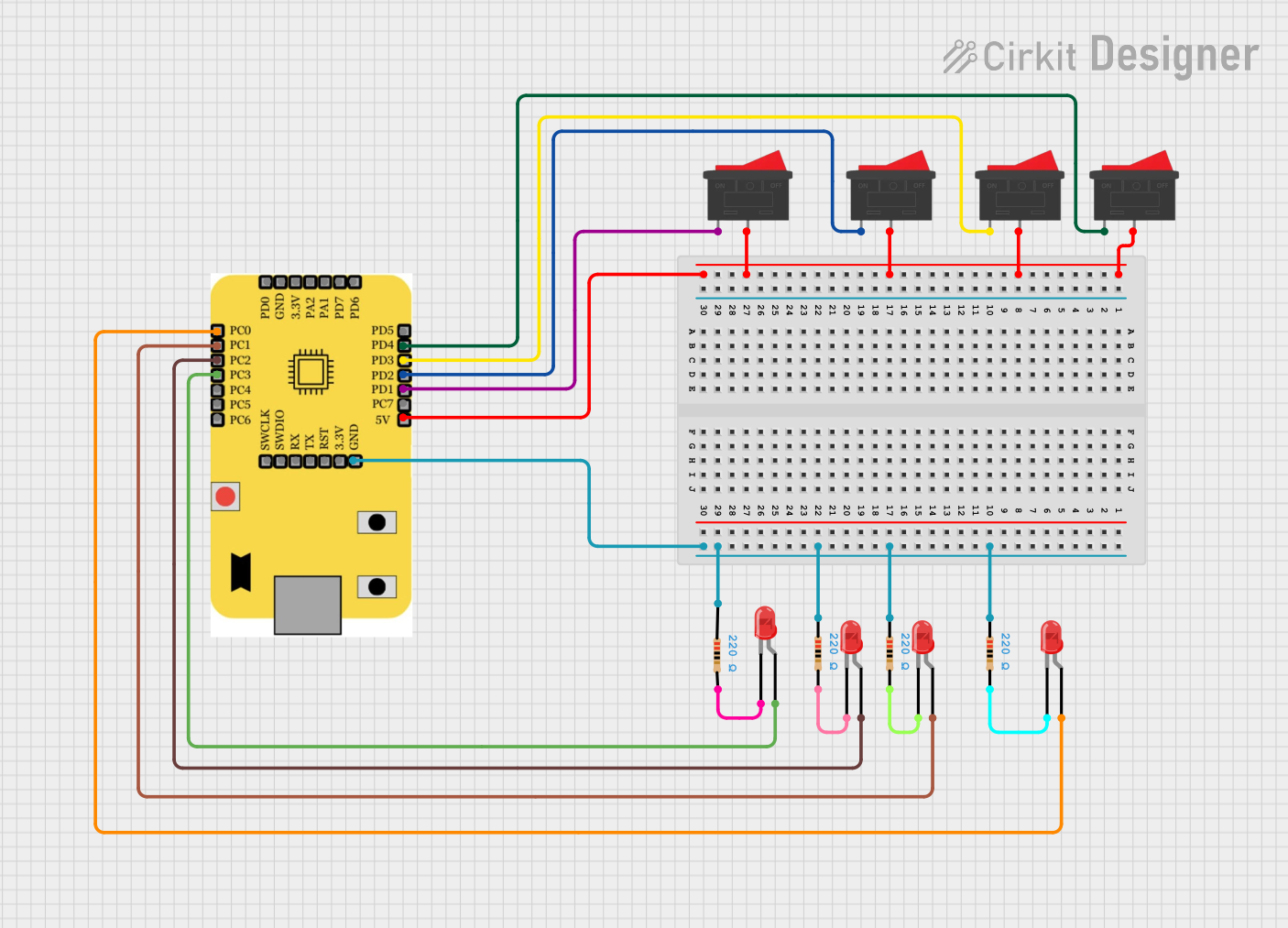
Circuit Documentation
Summary
This circuit is designed to read a 4-bit binary input from rocker switches and convert it to a 4-bit Gray code output, which is then displayed using LEDs. The circuit includes a microcontroller, multiple rocker switches, resistors, and LEDs. The microcontroller reads the binary input from the switches, performs the binary-to-Gray code conversion, and outputs the Gray code to the LEDs.
Component List
Microcontroller: mini squadron
- Pins: PC0, PC1, PC2, PC3, PC4, PC5, PC6, PD0, GND, 3.3V, PA2, PA1, PD7, PD6, PD5, PD4, PD3, PD2, PD1, PC7, 5V, SWCLK, SWDIO, RX, TX, RST
- Description: Main processing unit for the circuit.
- Purpose: Reads binary input, converts it to Gray code, and outputs the result.
Rocker Switch
- Pins: 1, 2
- Description: Mechanical switch with two positions.
- Purpose: Provides binary input to the microcontroller.
LED: Two Pin (red)
- Pins: Cathode, Anode
- Description: Light-emitting diode.
- Purpose: Displays the Gray code output.
Resistor
- Pins: Pin1, Pin2
- Description: 220 Ohms resistor.
- Purpose: Limits current to the LEDs.
Wiring Details
Microcontroller: mini squadron
- 5V: Connected to pin 2 of all Rocker Switches.
- GND: Connected to pin1 of all Resistors.
- PC0: Connected to the anode of LED 1.
- PC1: Connected to the anode of LED 2.
- PC2: Connected to the anode of LED 3.
- PC3: Connected to the anode of LED 4.
- PD1: Connected to pin 1 of Rocker Switch 1.
- PD2: Connected to pin 1 of Rocker Switch 2.
- PD3: Connected to pin 1 of Rocker Switch 3.
- PD4: Connected to pin 1 of Rocker Switch 4.
Rocker Switch 1
- Pin 1: Connected to PD1 of the microcontroller.
- Pin 2: Connected to 5V of the microcontroller.
Rocker Switch 2
- Pin 1: Connected to PD2 of the microcontroller.
- Pin 2: Connected to 5V of the microcontroller.
Rocker Switch 3
- Pin 1: Connected to PD3 of the microcontroller.
- Pin 2: Connected to 5V of the microcontroller.
Rocker Switch 4
- Pin 1: Connected to PD4 of the microcontroller.
- Pin 2: Connected to 5V of the microcontroller.
LED 1
- Anode: Connected to PC0 of the microcontroller.
- Cathode: Connected to pin 2 of Resistor 1.
LED 2
- Anode: Connected to PC1 of the microcontroller.
- Cathode: Connected to pin 2 of Resistor 2.
LED 3
- Anode: Connected to PC2 of the microcontroller.
- Cathode: Connected to pin 2 of Resistor 3.
LED 4
- Anode: Connected to PC3 of the microcontroller.
- Cathode: Connected to pin 2 of Resistor 4.
Resistor 1
- Pin 1: Connected to GND of the microcontroller.
- Pin 2: Connected to the cathode of LED 1.
Resistor 2
- Pin 1: Connected to GND of the microcontroller.
- Pin 2: Connected to the cathode of LED 2.
Resistor 3
- Pin 1: Connected to GND of the microcontroller.
- Pin 2: Connected to the cathode of LED 3.
Resistor 4
- Pin 1: Connected to GND of the microcontroller.
- Pin 2: Connected to the cathode of LED 4.
Documented Code
// Included the required header files
#include <stdio.h>
#include <debug.h>
#include <ch32v00x.h>

// Function to calculate Binary to Gray Code
uint8_t BinaryToGray(uint8_t binary)
{
    return (binary >> 1) ^ binary;
}

// Configuring GPIO Pins
void GPIO_Config(void)
{
    GPIO_InitTypeDef GPIO_InitStructure = {0}; // Structure variable used for GPIO configuration

    // Enable clock for Port D (Input) and Port C (Output)
    RCC_APB2PeriphClockCmd(RCC_APB2Periph_GPIOD, ENABLE);
    RCC_APB2PeriphClockCmd(RCC_APB2Periph_GPIOC, ENABLE);

    // Input Pins Configuration (Switches: PD1 = LSB, PD4 = MSB)
    GPIO_InitStructure.GPIO_Pin = GPIO_Pin_1 | GPIO_Pin_2 | GPIO_Pin_3 | GPIO_Pin_4;
    GPIO_InitStructure.GPIO_Mode = GPIO_Mode_IPU; // Input Pull-Up
    GPIO_Init(GPIOD, &GPIO_InitStructure);

    // Output Pins Configuration (LEDs: PC0 = LSB, PC3 = MSB)
    GPIO_InitStructure.GPIO_Pin = GPIO_Pin_0 | GPIO_Pin_1 | GPIO_Pin_2 | GPIO_Pin_3;
    GPIO_InitStructure.GPIO_Mode = GPIO_Mode_Out_PP; // Output Push-Pull
    GPIO_InitStructure.GPIO_Speed = GPIO_Speed_50MHz;
    GPIO_Init(GPIOC, &GPIO_InitStructure);
}

// Main Function
int main()
{
    uint8_t binary_input = 0;  // Stores 4-bit binary input
    uint8_t gray_output = 0;   // Stores 4-bit Gray code output

    NVIC_PriorityGroupConfig(NVIC_PriorityGroup_2);
    SystemCoreClockUpdate();
    Delay_Init();
    GPIO_Config();

    while (1)
    {
        // Read Binary Input from switches (PD1 = LSB to PD4 = MSB)
        binary_input = 0;
        binary_input |= GPIO_ReadInputDataBit(GPIOD, GPIO_Pin_1) << 0; // Bit 0 (LSB)
        binary_input |= GPIO_ReadInputDataBit(GPIOD, GPIO_Pin_2) << 1; // Bit 1
        binary_input |= GPIO_ReadInputDataBit(GPIOD, GPIO_Pin_3) << 2; // Bit 2
        binary_input |= GPIO_ReadInputDataBit(GPIOD, GPIO_Pin_4) << 3; // Bit 3 (MSB)

        // Convert Binary to Gray Code
        gray_output = BinaryToGray(binary_input);

        // Write Gray Code Output to LEDs (PC0 = LSB to PC3 = MSB)
        GPIO_WriteBit(GPIOC, GPIO_Pin_0, (BitAction)(gray_output & 0x01)); // Gray Bit 0 (LSB)
        GPIO_WriteBit(GPIOC, GPIO_Pin_1, (BitAction)((gray_output >> 1) & 0x01)); // Gray Bit 1
        GPIO_WriteBit(GPIOC, GPIO_Pin_2, (BitAction)((gray_output >> 2) & 0x01)); // Gray Bit 2
        GPIO_WriteBit(GPIOC, GPIO_Pin_3, (BitAction)((gray_output >> 3) & 0x01)); // Gray Bit 3 (MSB)
    }
}