
ESP32-Based Smart Irrigation System with DHT11 and Soil Moisture Sensor
View and Edit Project In Cirkit Designer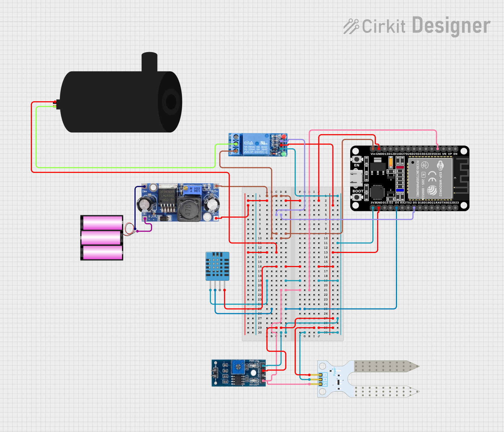
Smart Irrigation System Documentation
Summary
This document provides a detailed overview of a smart irrigation system designed using an ESP32 microcontroller. The system includes a DHT11 humidity and temperature sensor, a soil moisture sensor, a soil moisture module, a 1-channel relay, a water pump, a DC-DC converter, and a 12V battery. The ESP32 reads data from the sensors and controls the water pump via the relay based on the soil moisture level.
Component List
ESP32 (30 pin)
- Description: A powerful microcontroller with Wi-Fi and Bluetooth capabilities.
- Pins: EN, VP, VN, D34, D35, D32, D33, D25, D26, D27, D14, D12, D13, GND, Vin, D23, D22, TX0, RX0, D21, D19, D18, D5, TX2, RX2, D4, D2, D15, 3V3
DHT11 Humidity and Temperature Sensor
- Description: A sensor used to measure humidity and temperature.
- Pins: VDD, DATA, NULL, GND
Battery 12V
- Description: A 12V battery used to power the system.
- Pins: +, -
Water Pump
- Description: A pump used to irrigate the soil.
- Pins: positive, negative
Soil Moisture Sensor
- Description: A sensor used to measure the moisture level in the soil.
- Pins: VCC, GND, SIG
Soil Moisture Module
- Description: A module that interfaces with the soil moisture sensor.
- Pins: VCC, GND, D0, A0
1 Channel Relay 5V
- Description: A relay used to control the water pump.
- Pins: VCC, GND, IN, NC, COM, NO
DC-DC Converter
- Description: A converter used to step down the voltage from the 12V battery to a suitable level for the ESP32 and other components.
- Pins: +VCC IN, GND IN, +VCC OUT, GND OUT
Wiring Details
ESP32 (30 pin)
- Vin: Connected to +VCC OUT of the DC-DC converter and NO of the 1 Channel Relay 5V.
- GND: Connected to GND OUT of the DC-DC converter and negative of the water pump.
- D5: Connected to IN of the 1 Channel Relay 5V.
- D34: Connected to SIG of the Soil Moisture Sensor and A0 of the Soil Moisture Module.
- D4: Connected to DATA of the DHT11 Humidity and Temperature Sensor.
- 3V3: Connected to VCC of the DHT11 Humidity and Temperature Sensor, Soil Moisture Module, Soil Moisture Sensor, and 1 Channel Relay 5V.
DHT11 Humidity and Temperature Sensor
- VDD: Connected to 3V3 of the ESP32.
- DATA: Connected to D4 of the ESP32.
- GND: Connected to GND of the ESP32.
Battery 12V
- +: Connected to +VCC IN of the DC-DC converter.
- -: Connected to GND IN of the DC-DC converter.
Water Pump
- positive: Connected to COM of the 1 Channel Relay 5V.
- negative: Connected to GND of the ESP32.
Soil Moisture Sensor
- VCC: Connected to 3V3 of the ESP32.
- GND: Connected to GND of the ESP32.
- SIG: Connected to D34 of the ESP32.
Soil Moisture Module
- VCC: Connected to 3V3 of the ESP32.
- GND: Connected to GND of the ESP32.
- A0: Connected to D34 of the ESP32.
1 Channel Relay 5V
- VCC: Connected to 3V3 of the ESP32.
- GND: Connected to GND of the ESP32.
- IN: Connected to D5 of the ESP32.
- NO: Connected to Vin of the ESP32.
- COM: Connected to positive of the water pump.
DC-DC Converter
- +VCC IN: Connected to + of the 12V battery.
- GND IN: Connected to - of the 12V battery.
- +VCC OUT: Connected to Vin of the ESP32 and NO of the 1 Channel Relay 5V.
- GND OUT: Connected to GND of the ESP32 and negative of the water pump.
Documented Code
#include <DHT.h>
#include <DHT_U.h>

// Pin definitions
#define DHT_PIN 4          // DHT11 data pin connected to D4 of ESP32
#define SOIL_MOISTURE_PIN 34 // Analog pin for soil moisture sensor connected to D34
#define RELAY_PIN 5         // Relay control pin connected to D5 of ESP32

// DHT sensor setup
#define DHT_TYPE DHT11
DHT dht(DHT_PIN, DHT_TYPE);

// Threshold for soil moisture (adjust based on testing)
#define MOISTURE_THRESHOLD 500

void setup() {
  // Initialize Serial Monitor
  Serial.begin(115200);
  Serial.println("Initializing Smart Irrigation System...");

  // Initialize DHT11 sensor
  dht.begin();
  Serial.println("[INFO] DHT11 sensor initialized.");

  // Initialize relay pin
  pinMode(RELAY_PIN, OUTPUT);
  digitalWrite(RELAY_PIN, LOW); // Ensure pump is initially off
  Serial.println("[INFO] Relay initialized. Pump is OFF.");

  // Soil moisture sensor setup
  pinMode(SOIL_MOISTURE_PIN, INPUT);
  Serial.println("[INFO] Soil moisture sensor initialized.");
  Serial.println("========================================");
}

void loop() {
  Serial.println("Reading sensor data...");

  // Simulating dummy data for testing purposes:
  float temperature = 25.0;   // Dummy temperature value (in Celsius)
  float humidity = 60.0;      // Dummy humidity value (in %)

  // Simulating soil moisture data (random between 0-1023 for 10-bit ADC)
  int soilMoistureValue = random(0, 1024);

  // Display the simulated data
  Serial.print("[DHT11] Temperature: ");
  Serial.print(temperature);
  Serial.println(" °C");

  Serial.print("[DHT11] Humidity: ");
  Serial.print(humidity);
  Serial.println(" %");

  // Display soil moisture value
  Serial.print("[SOIL] Moisture Level: ");
  Serial.println(soilMoistureValue);

  // Control water pump based on soil moisture level
  if (soilMoistureValue < MOISTURE_THRESHOLD) {
    Serial.println("[RELAY] Soil is dry. Turning ON the pump...");
    digitalWrite(RELAY_PIN, HIGH); // Turn on relay (pump ON)
  } else {
    Serial.println("[RELAY] Soil is wet. Turning OFF the pump...");
    digitalWrite(RELAY_PIN, LOW); // Turn off relay (pump OFF)
  }

  Serial.println("----------------------------------------");
  // Wait for a few seconds before the next loop
  delay(2000);
}
This code initializes the sensors and relay, reads data from the DHT11 and soil moisture sensor, and controls the water pump based on the soil moisture level. The system prints the sensor data and pump status to the Serial Monitor for debugging and monitoring purposes.