
ESP32-S3 Based Smart IoT Distance Sensor with Ethernet Connectivity
View and Edit Project In Cirkit Designer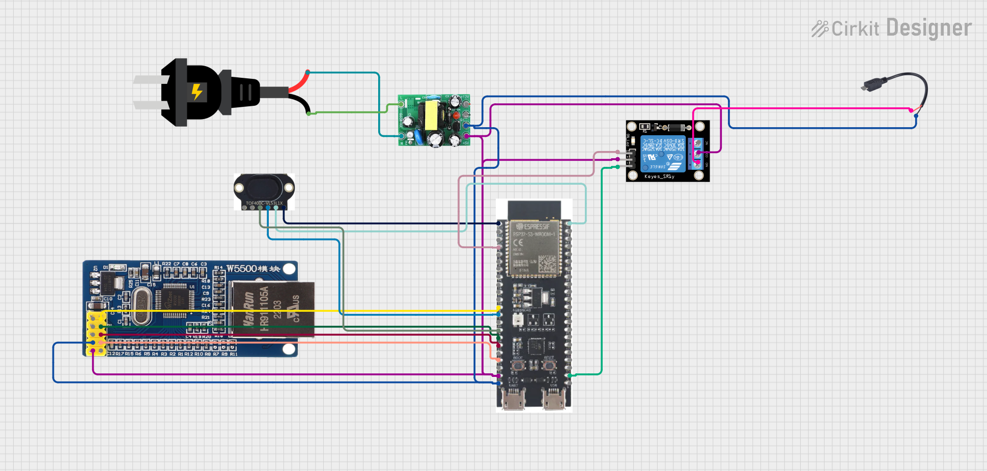
Circuit Documentation
Summary
The circuit in question appears to be a microcontroller-based system designed to interface with a relay module, an Ethernet module, and a time-of-flight sensor. The ESP32-S3 microcontroller is the central processing unit, controlling the relay and communicating with the Ethernet module and the VL53L1X sensor. The AC source and actodc converter provide power to the system, with the Micro USB to Cable component likely serving as a power input or programming interface for the microcontroller.
Component List
KY-019 Relay Module 1 Channel
- Description: A relay module that can be used to control high power devices.
- Pins: S (Signal), 5V, GND (Ground), NC (Normally Closed), COM (Common), NO (Normally Open)
AC Source
- Description: An alternating current power source.
- Pins: - (Negative), + (Positive)
VL53L1X
- Description: A time-of-flight sensor for accurate distance measurement.
- Pins: VIN (Voltage In), GND (Ground), SDA (Serial Data), SCL (Serial Clock), INT (Interrupt), SHUT (Shutdown)
Module Ethernet W5500
- Description: An Ethernet module that allows microcontrollers to connect to a network.
- Pins: NC (Not Connected), INT (Interrupt), RST (Reset), GND (Ground), 5V, SCK (Serial Clock), SS (Slave Select), MOSI (Master Out Slave In), MISO (Master In Slave Out), 3.3V
ESP32-S3
- Description: A microcontroller with Wi-Fi and Bluetooth capabilities.
- Pins: Multiple GPIOs, 3v3, EN (Enable), 5V, GND (Ground)
Actodc
- Description: A power converter that converts AC to DC.
- Pins: 12v, - (Negative), 5v, live, neutral
Micro USB to Cable (2 Pin)
- Description: A Micro USB connector with breakout to two pins.
- Pins: Micro USB, + (Positive), - (Negative)
Wiring Details
KY-019 Relay Module 1 Channel
- Signal (S): Connected to GPIO4 of ESP32-S3
- 5V: Shared connection with ESP32-S3, Module Ethernet W5500, and actodc
- GND: Connected to GND of ESP32-S3
- NO (Normally Open): Connected to + of Micro USB to Cable (2 Pin)
- COM (Common): Shared connection with 5V
AC Source
- Negative (-): Connected to neutral of actodc
- Positive (+): Connected to live of actodc
VL53L1X
- VIN: Connected to 3v3 of ESP32-S3
- GND: Connected to GND of ESP32-S3
- SDA: Connected to GPIO8 of ESP32-S3
- SCL: Connected to GPIO9 of ESP32-S3
Module Ethernet W5500
- 5V: Shared connection with ESP32-S3, KY-019 Relay module, and actodc
- GND: Shared connection with ESP32-S3, actodc, and Micro USB to Cable (2 Pin)
- SCK: Connected to GPIO18 of ESP32-S3
- SS: Connected to GPIO10 of ESP32-S3
- MOSI: Connected to GPIO11 of ESP32-S3
- MISO: Connected to GPIO13 of ESP32-S3
ESP32-S3
- 3v3: Connected to VIN of VL53L1X
- 5V: Shared connection with KY-019 Relay module, Module Ethernet W5500, and actodc
- GND: Shared connection with KY-019 Relay module, Module Ethernet W5500, VL53L1X, actodc, and Micro USB to Cable (2 Pin)
- GPIOs: Connected to various components as detailed above
Actodc
- 5v: Shared connection with ESP32-S3, Module Ethernet W5500, and KY-019 Relay module
- Neutral: Connected to Negative (-) of AC Source
- Live: Connected to Positive (+) of AC Source
- - (Negative): Shared connection with Module Ethernet W5500, ESP32-S3, and Micro USB to Cable (2 Pin)
Micro USB to Cable (2 Pin)
- + (Positive): Connected to NO of KY-019 Relay module
- - (Negative): Shared connection with Module Ethernet W5500, ESP32-S3, and actodc
Documented Code
No code was provided for the microcontrollers in the circuit. Therefore, this section is left blank until the relevant code is supplied for documentation.