
Circuit Documentation
Summary
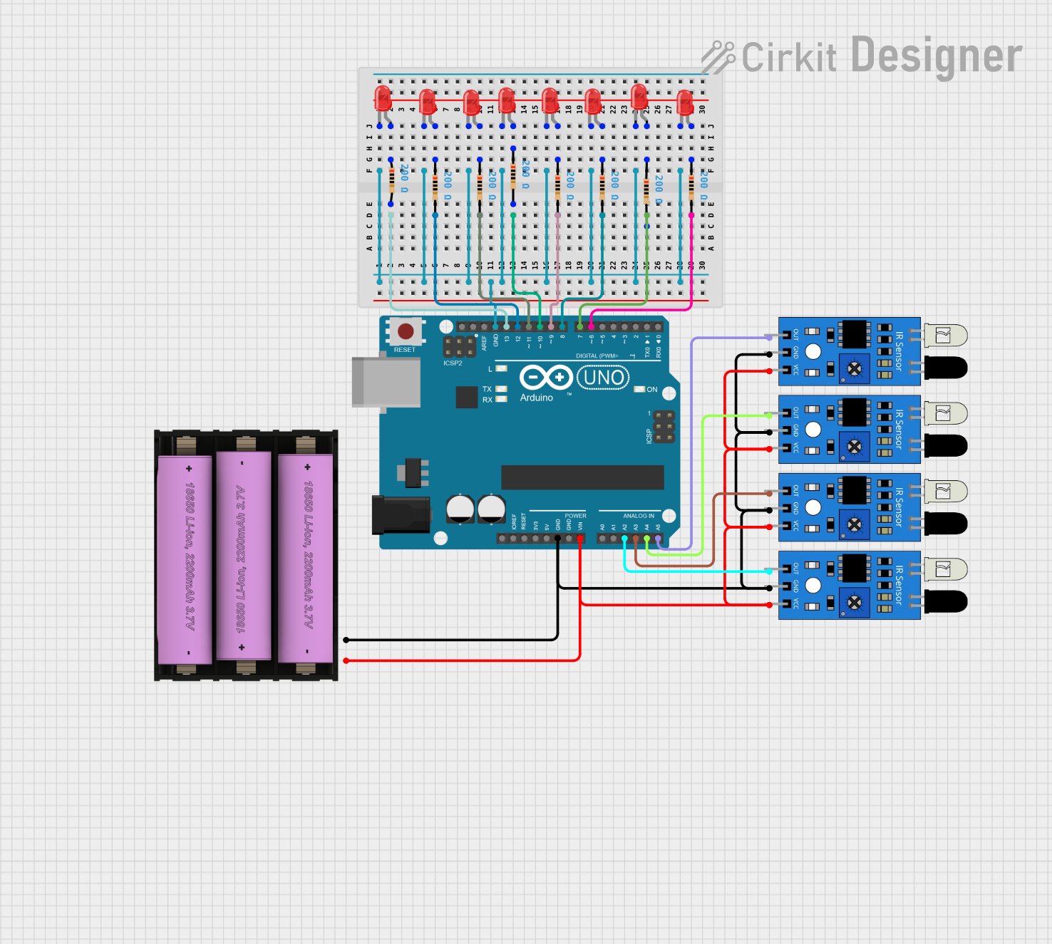
This circuit is designed around an Arduino UNO microcontroller and includes a series of red LEDs, resistors, and IR sensors. The LEDs are connected to the digital pins of the Arduino through individual resistors, which suggests that they are intended to be controlled independently, likely for signaling or display purposes. The IR sensors are connected to both the power supply and analog input pins, indicating their use for sensing applications. The circuit is powered by a 7V battery connected to the Arduino's Vin pin and the ground.
Component List
Microcontroller
- Arduino UNO: A microcontroller board based on the ATmega328P. It has 14 digital input/output pins, 6 analog inputs, a USB connection, a power jack, an ICSP header, and a reset button.
LEDs
- LED: Two Pin (red): A basic red light-emitting diode with an anode and cathode for emitting red light when powered.
Resistors
- Resistor: A passive two-terminal electrical component with a resistance of 200 Ohms, used to limit the current flowing through the LEDs.
IR Sensors
- IR Sensor: An infrared sensor with an output pin, ground, and Vcc for detecting infrared radiation.
Power Supply
- Set battery (7v): A power source providing a 7V output, used to power the circuit.
Wiring Details
Arduino UNO
- Digital Pins (D6-D13): Connected to one side of the resistors.
- Analog Pins (A2-A5): Connected to the output of the IR sensors.
- GND: Connected to the cathodes of all LEDs and the ground of all IR sensors.
- Vin: Connected to the positive terminal of the 7V battery.
- 5V, 3.3V, IOREF, Reset, AREF, Unused Pins: Not connected in this circuit.
LEDs
- Cathode: Connected to the Arduino's GND.
- Anode: Connected to the other side of the corresponding resistor.
Resistors
- One Side (pin1): Connected to the anode of the corresponding LED.
- Other Side (pin2): Connected to the corresponding digital pin on the Arduino UNO.
IR Sensors
- Out: Connected to the corresponding analog pin on the Arduino UNO.
- GND: Connected to the negative terminal of the 7V battery and Arduino's GND.
- Vcc: Connected to the positive terminal of the 7V battery and Arduino's Vin.
Set battery (7v)
- Positive (+): Connected to the Vcc of all IR sensors and Arduino's Vin.
- Negative (-): Connected to the GND of all IR sensors and Arduino's GND.
Documented Code
Arduino UNO Code (sketch.ino)
void setup() {
  // put your setup code here, to run once:

}

void loop() {
  // put your main code here, to run repeatedly:

}
Additional Notes
- The provided code is a template and does not contain any functionality. It needs to be populated with the logic to control the LEDs and read the IR sensors.
- The
setup()function is intended for initialization code that runs once at the start, such as pin mode declarations. - The
loop()function is for code that runs continuously, which would include the main logic for reading sensors and controlling the LEDs. - The actual behavior of the circuit will be determined by the code that is written and uploaded to the Arduino UNO.