
ESP32-Controlled Multi-Motor System with Relay Switching and OLED Display
View and Edit Project In Cirkit Designer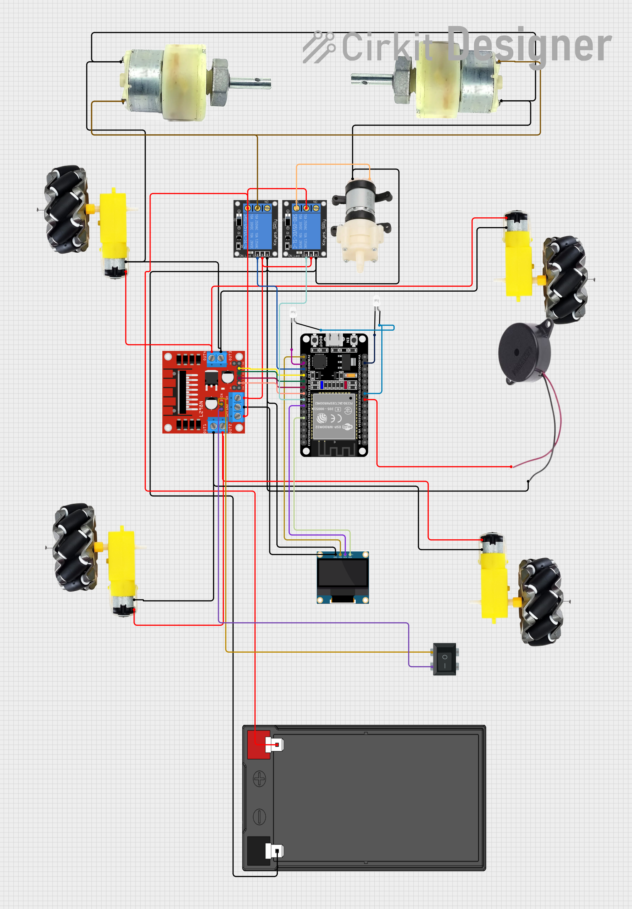
Circuit Documentation
Summary
The circuit in question appears to be a control system that utilizes an ESP32 microcontroller to manage various components including relays, motors, an OLED display, and a buzzer. The system is powered by a 12V 7Ah battery and includes a motor driver for controlling the motors. The relays are used to switch higher power loads, such as the motors and a water pump. The OLED display provides a user interface or status display, and the buzzer can be used for audible alerts. The ESP32 is the central processing unit that receives inputs, processes them, and controls the outputs based on the programmed logic.
Component List
1-Channel Relay (5V 10A)
- Description: A relay capable of switching up to 10A at 5V.
- Pins: NC (Normally Closed), signal, C (Common), power, NO (Normally Open), ground.
0.96" OLED
- Description: A small OLED display for visual output.
- Pins: GND (Ground), VDD (Power), SCK (Serial Clock), SDA (Serial Data).
Motor and Wheels
- Description: A set of motors with attached wheels for mobility.
- Pins: vcc (Power), GND (Ground).
L298N DC Motor Driver
- Description: A motor driver module for controlling the direction and speed of DC motors.
- Pins: OUT1, OUT2, 12V, GND, 5V, OUT3, OUT4, 5V-ENA-JMP-I, 5V-ENA-JMP-O, +5V-J1, +5V-J2, ENA, IN1, IN2, IN3, IN4, ENB.
Rocker Switch 4 Pin
- Description: A switch to control power flow.
- Pins: 1, 3, 2, 4.
12V Geared Motor
- Description: A motor designed for high torque at low speeds.
- Pins: Terminal 1, Terminal 2.
Mini Diaphragm Water Pump
- Description: A pump for moving water.
- Pins: Positive (+), Negative (-).
12V 7Ah Battery
- Description: A rechargeable battery providing the power source for the circuit.
- Pins: 12v + (Positive), 12v - (Negative).
ESP32 (30 pin)
- Description: A microcontroller with Wi-Fi and Bluetooth capabilities.
- Pins: EN, VP, VN, D34, D35, D32, D33, D25, D26, D27, D14, D12, D13, GND, Vin, D23, D22, TX0, RX0, D21, D19, D18, D5, TX2, RX2, D4, D2, D15, 3V3.
LED: Two Pin (white)
- Description: A white LED for visual indication.
- Pins: cathode, anode.
Buzzer
- Description: An audible alert device.
- Pins: POSITIVE, NEGATIVE.
Wiring Details
1-Channel Relay (5V 10A)
- NC connected to L298N DC motor driver 12V and 12V 7Ah Battery 12v +.
- Signal connected to ESP32 D15.
- C connected to 12V Geared Motor Terminal 2 and 12V 7Ah Battery 12v +.
- Power connected to L298N DC motor driver 5V.
- NO not connected.
- Ground connected to 12V 7Ah Battery 12v -.
0.96" OLED
- GND connected to 12V Geared Motor Terminal 1 and various other GND connections.
- VDD connected to ESP32 3V3.
- SCK connected to ESP32 D18.
- SDA connected to ESP32 D21.
Motor and Wheels
- vcc connected to L298N DC motor driver OUT4 and OUT2.
- GND connected to L298N DC motor driver OUT1 and various other GND connections.
L298N DC Motor Driver
- 12V connected to 1-Channel Relay NC and 12V 7Ah Battery 12v +.
- GND connected to 12V Geared Motor Terminal 1 and various other GND connections.
- 5V connected to 1-Channel Relay power.
- OUT1/OUT2/OUT3/OUT4 connected to Motor and Wheels vcc/GND.
- 5V-ENA-JMP-I connected to Rocker Switch 4 Pin 4.
- 5V-ENA-JMP-O connected to Rocker Switch 4 Pin 2.
- IN1/IN2/IN3/IN4 connected to ESP32 TX2/RX2/D4/D2.
Rocker Switch 4 Pin
- Pin 4 connected to L298N DC motor driver 5V-ENA-JMP-I.
- Pin 2 connected to L298N DC motor driver 5V-ENA-JMP-O.
12V Geared Motor
- Terminal 1 connected to various GND connections.
- Terminal 2 connected to 1-Channel Relay C.
Mini Diaphragm Water Pump
- Positive (+) connected to 1-Channel Relay NC.
- Negative (-) connected to various GND connections.
12V 7Ah Battery
- 12v + connected to 1-Channel Relay NC and L298N DC motor driver 12V.
- 12v - connected to various GND connections.
ESP32 (30 pin)
- Various pins connected to 0.96" OLED, L298N DC motor driver, 1-Channel Relay signal, Buzzer, and LEDs.
LED: Two Pin (white)
- Anode connected to ESP32 D26.
- Cathode connected to ESP32 GND.
Buzzer
- POSITIVE connected to ESP32 D25.
- NEGATIVE connected to various GND connections.
Documented Code
No code was provided for the microcontroller(s) in the circuit. The documentation of the code would typically include a description of the functionality implemented, the setup and loop functions for an Arduino-based system, or the main function for other microcontroller systems. It would also include any functions or libraries used to control the peripherals such as the motors, OLED display, and relays.