Cirkit Designer
Your all-in-one circuit design IDE
Home /
Project Documentation
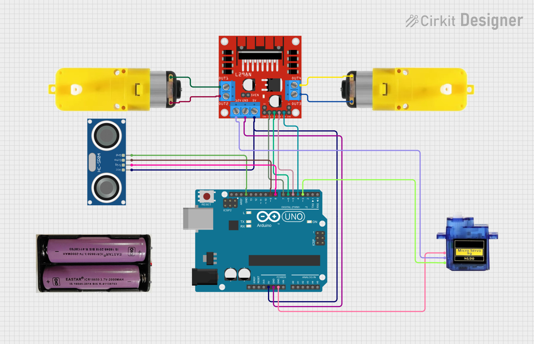
Arduino UNO-Based Distance Measuring Robot with Motor Control and Servo
Circuit Documentation
Summary
This circuit is designed to control a motor driver, an ultrasonic sensor, and a servo motor using an Arduino UNO. The ultrasonic sensor measures distance, and based on the distance, an LED blinks a specified number of times. The results are also printed to the serial monitor.
Component List
Arduino UNO
- Description: A microcontroller board based on the ATmega328P.
- Pins: UNUSED, IOREF, Reset, 3.3V, 5V, GND, Vin, A0, A1, A2, A3, A4, A5, SCL, SDA, AREF, D13, D12, D11, D10, D9, D8, D7, D6, D5, D4, D3, D2, D1, D0
Motor with reducer
- Description: A DC motor with a gear reducer.
- Pins: 3 - 6 VCC, GND
L298N DC motor driver
- Description: A dual H-Bridge motor driver.
- Pins: OUT1, OUT2, 12V, GND, 5V, OUT3, OUT4, 5V-ENA-JMP-I, 5V-ENA-JMP-O, +5V-J1, +5V-J2, ENA, IN1, IN2, IN3, IN4, ENB
HC-SR04 Ultrasonic Sensor
- Description: An ultrasonic distance sensor.
- Pins: VCC, TRIG, ECHO, GND
Micro servo 9G
- Description: A small servo motor.
- Pins: GND, +5V, PWM
7.4v Battery
- Description: A 7.4V battery for powering the circuit.
- Pins: +, -
Wiring Details
Arduino UNO
- 5V: Connected to 5V pin of L298N DC motor driver and VCC pin of HC-SR04 Ultrasonic Sensor.
- GND: Connected to GND pin of L298N DC motor driver, GND pin of Micro servo 9G, and GND pin of HC-SR04 Ultrasonic Sensor.
- D9: Connected to ECHO pin of HC-SR04 Ultrasonic Sensor.
- D8: Connected to TRIG pin of HC-SR04 Ultrasonic Sensor.
- D7: Connected to IN1 pin of L298N DC motor driver.
- D6: Connected to IN2 pin of L298N DC motor driver.
- D5: Connected to IN3 pin of L298N DC motor driver.
- D4: Connected to IN4 pin of L298N DC motor driver.
- D3: Connected to PWM pin of Micro servo 9G.
Motor with reducer (Instance 1)
- 3 - 6 VCC: Connected to OUT1 pin of L298N DC motor driver.
- GND: Connected to OUT2 pin of L298N DC motor driver.
Motor with reducer (Instance 2)
- 3 - 6 VCC: Connected to OUT3 pin of L298N DC motor driver.
- GND: Connected to OUT4 pin of L298N DC motor driver.
L298N DC motor driver
- 5V: Connected to 5V pin of Arduino UNO and VCC pin of HC-SR04 Ultrasonic Sensor.
- GND: Connected to GND pin of Arduino UNO.
- IN1: Connected to D7 pin of Arduino UNO.
- IN2: Connected to D6 pin of Arduino UNO.
- IN3: Connected to D5 pin of Arduino UNO.
- IN4: Connected to D4 pin of Arduino UNO.
- OUT1: Connected to 3 - 6 VCC pin of Motor with reducer (Instance 1).
- OUT2: Connected to GND pin of Motor with reducer (Instance 1).
- OUT3: Connected to 3 - 6 VCC pin of Motor with reducer (Instance 2).
- OUT4: Connected to GND pin of Motor with reducer (Instance 2).
- 12V: Connected to +5V pin of Micro servo 9G.
HC-SR04 Ultrasonic Sensor
- VCC: Connected to 5V pin of Arduino UNO and 5V pin of L298N DC motor driver.
- GND: Connected to GND pin of Arduino UNO.
- ECHO: Connected to D9 pin of Arduino UNO.
- TRIG: Connected to D8 pin of Arduino UNO.
Micro servo 9G
- GND: Connected to GND pin of Arduino UNO.
- +5V: Connected to 12V pin of L298N DC motor driver.
- PWM: Connected to D3 pin of Arduino UNO.
Code Documentation
/*
 * This Arduino sketch controls a motor driver, ultrasonic sensor, and a servo.
 * The ultrasonic sensor measures distance, and based on the distance, the LED
 * blinks a specified number of times. The results are also printed to the
 * serial monitor.
 */

#include <Servo.h>

// Pin definitions
const int trigPin = 8;
const int echoPin = 9;
const int ledPin = 13;
const int servoPin = 3;
const int motorIn1 = 7;
const int motorIn2 = 6;
const int motorIn3 = 5;
const int motorIn4 = 4;

Servo myServo;

void setup() {
  // Initialize serial communication
  Serial.begin(9600);

  // Initialize pins
  pinMode(trigPin, OUTPUT);
  pinMode(echoPin, INPUT);
  pinMode(ledPin, OUTPUT);
  pinMode(motorIn1, OUTPUT);
  pinMode(motorIn2, OUTPUT);
  pinMode(motorIn3, OUTPUT);
  pinMode(motorIn4, OUTPUT);

  // Attach the servo
  myServo.attach(servoPin);
}

void loop() {
  // Measure distance
  long duration, distance;
  digitalWrite(trigPin, LOW);
  delayMicroseconds(2);
  digitalWrite(trigPin, HIGH);
  delayMicroseconds(10);
  digitalWrite(trigPin, LOW);
  duration = pulseIn(echoPin, HIGH);
  distance = (duration / 2) / 29.1;

  // Print distance to serial monitor
  Serial.print("Distance: ");
  Serial.print(distance);
  Serial.println(" cm");

  // Blink LED based on distance
  if (distance >= 3 && distance <= 5) {
    blinkLED(5);
  } else if (distance >= 10 && distance <= 20) {
    blinkLED(10);
  }

  // Small delay before next measurement
  delay(500);
}

void blinkLED(int times) {
  for (int i = 0; i < times; i++) {
    digitalWrite(ledPin, HIGH);
    delay(250);
    digitalWrite(ledPin, LOW);
    delay(250);
  }
}
This code initializes the pins for the ultrasonic sensor, motor driver, and servo motor. It measures the distance using the ultrasonic sensor and blinks an LED based on the measured distance. The results are printed to the serial monitor.