
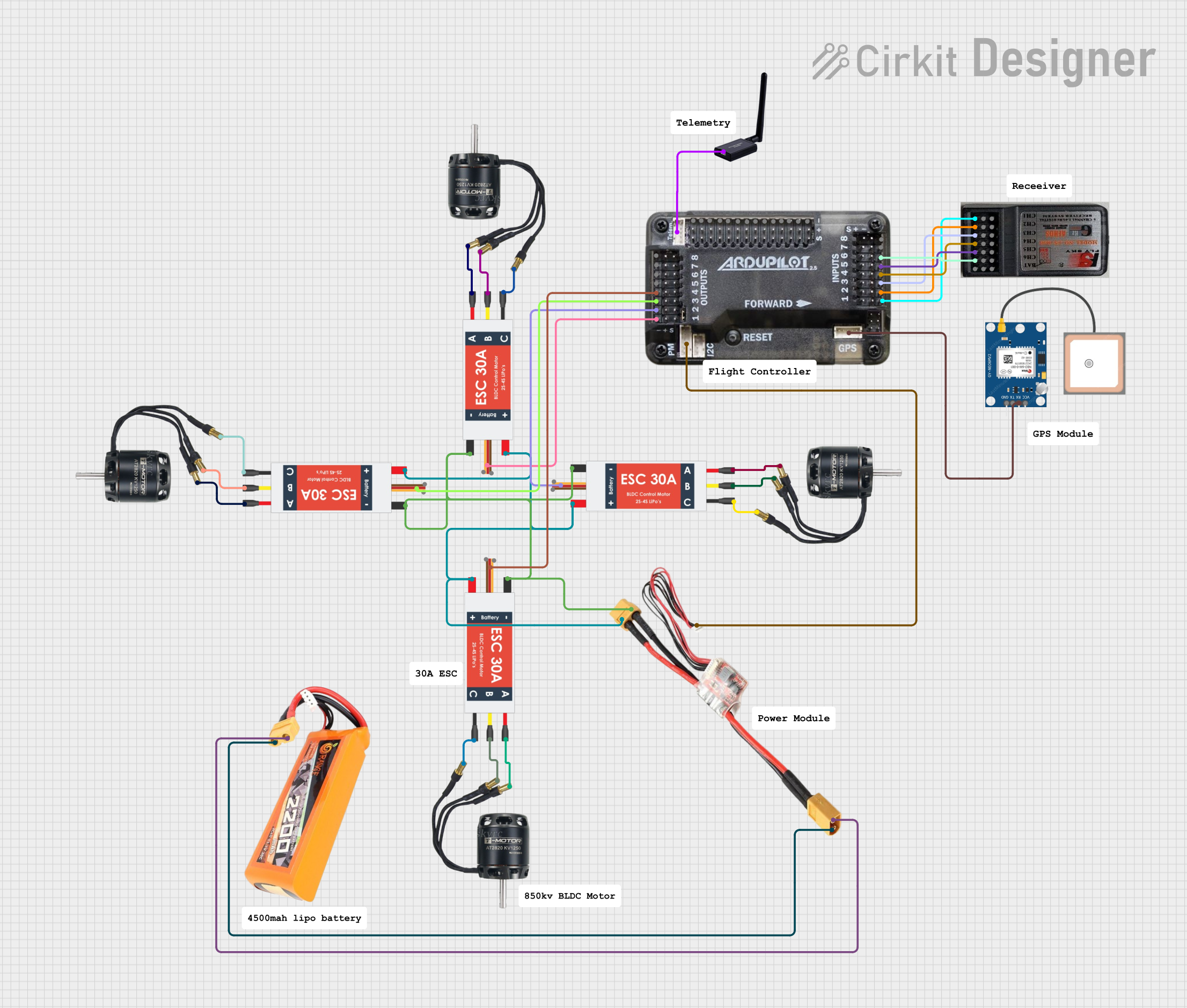
Circuit Documentation
Summary
This document provides a detailed overview of a circuit designed to control multiple BLDC motors using Electronic Speed Controllers (ESCs), powered by a LiPo battery, and managed by an APM 2.0 flight controller. The circuit also includes a GPS module, an RC receiver, a power module, and a telemetry module.
Component List
BLDC Motor
- Description: Brushless DC motor used for propulsion.
- Pins: Wire A, Wire B, Wire C
LiPo Battery 2200mAH 30C
- Description: Lithium Polymer battery providing power to the circuit.
- Pins: VCC, GND
Electronic Speed Controller (ESC)
- Description: Controls the speed of the BLDC motors.
- Pins: Battery VCC, Battery GND, Signal, 5V out, GND out, M1, M2, M3
GPS NEO 6M
- Description: GPS module for location tracking.
- Pins: VCC, RX, TX, GND
APM 2.0
- Description: Flight controller for managing the drone's operations.
- Pins: OUT1, OUT2, OUT3, OUT4, OUT5, OUT6, OUT7, OUT8, A0, A1, A2, A3, A4, A5, A6, A7, A8, A9, A10, A11, A12, A13, IN1, IN2, IN3, IN4, IN5, IN6, IN7, IN8, GPS, PM, telem
RC Receiver 6 Channels
- Description: Receives control signals from the remote controller.
- Pins: CH1, VCC, GND, CH2, CH3, CH4, CH5, CH6, Bind
Power Module
- Description: Distributes power to various components.
- Pins: in1, in neg, out plus, out neg, PM
Telemetry
- Description: Provides telemetry data for remote monitoring.
- Pins: telem
Wiring Details
BLDC Motor
- Wire A connected to ESC M3
- Wire B connected to ESC M2
- Wire C connected to ESC M1
LiPo Battery 2200mAH 30C
- VCC connected to Power Module out plus
- GND connected to Power Module out neg
Electronic Speed Controller (ESC)
- Battery VCC connected to:
- Power Module in1
- Other ESC Battery VCC pins
- Battery GND connected to:
- Power Module in neg
- Other ESC Battery GND pins
- 5V out connected to:
- APM 2.0 OUT1
- APM 2.0 OUT2
- APM 2.0 OUT3
- APM 2.0 OUT4
- M1 connected to BLDC Motor Wire C
- M2 connected to BLDC Motor Wire B
- M3 connected to BLDC Motor Wire A
GPS NEO 6M
- RX connected to APM 2.0 GPS
APM 2.0
- OUT1 connected to ESC 5V out
- OUT2 connected to ESC 5V out
- OUT3 connected to ESC 5V out
- OUT4 connected to ESC 5V out
- IN1 connected to RC Receiver GND
- IN2 connected to RC Receiver GND
- IN3 connected to RC Receiver GND
- IN4 connected to RC Receiver GND
- IN5 connected to RC Receiver GND
- IN6 connected to RC Receiver GND
- PM connected to Power Module PM
- telem connected to Telemetry telem
RC Receiver 6 Channels
- GND connected to APM 2.0 IN1
- GND connected to APM 2.0 IN2
- GND connected to APM 2.0 IN3
- GND connected to APM 2.0 IN4
- GND connected to APM 2.0 IN5
- GND connected to APM 2.0 IN6
Power Module
- in1 connected to ESC Battery VCC
- in neg connected to ESC Battery GND
- out plus connected to LiPo Battery VCC
- out neg connected to LiPo Battery GND
- PM connected to APM 2.0 PM
Telemetry
- telem connected to APM 2.0 telem
Code
No code is provided for this circuit.
This document provides a comprehensive overview of the circuit, including a summary, component list, wiring details, and code documentation. Each section is designed to offer clear and concise information for understanding and replicating the circuit.