
Arduino UNO-Based Battery-Powered Robotic Car with Ultrasonic Sensor and Optical Encoders
View and Edit Project In Cirkit Designer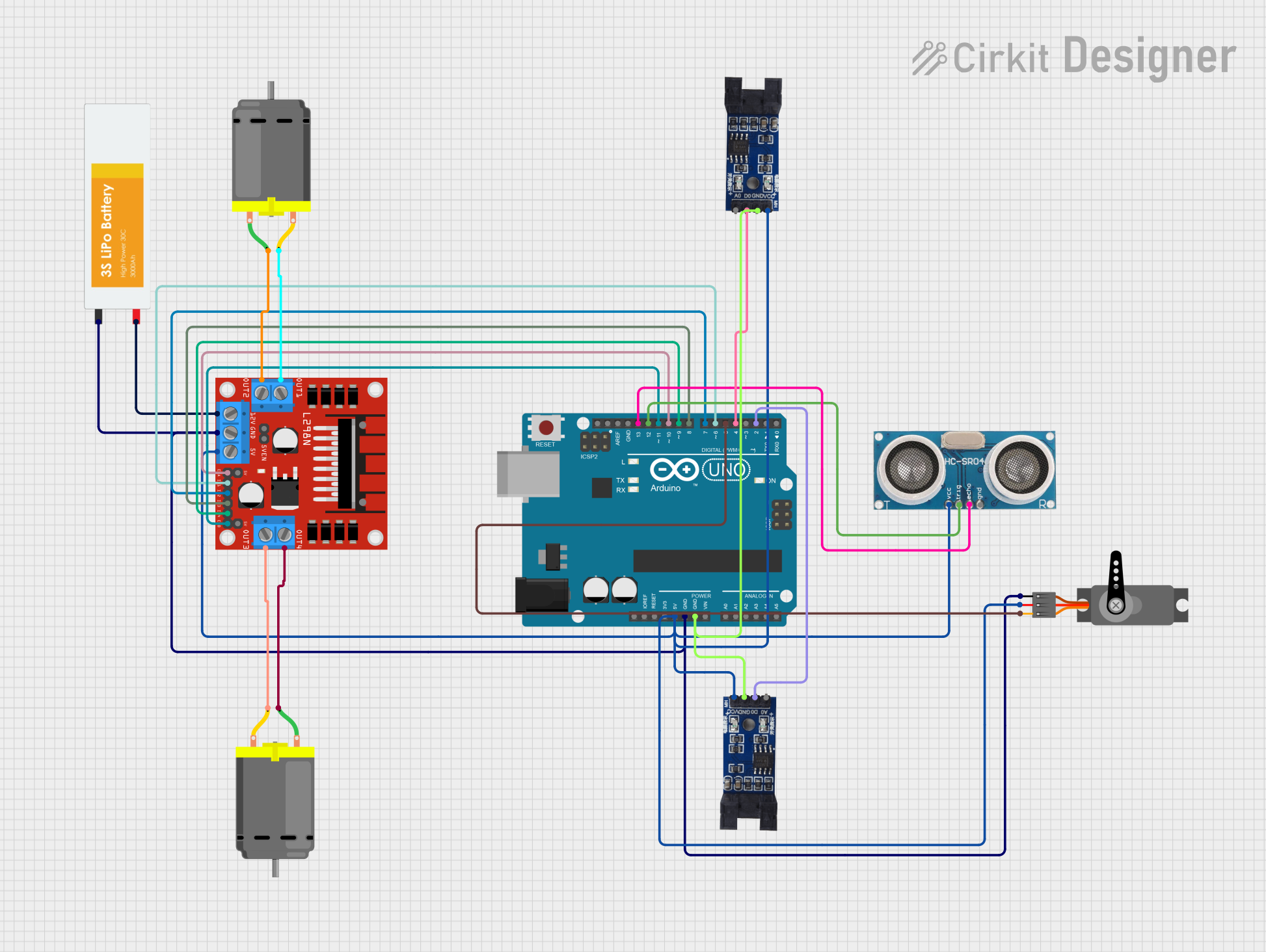
Circuit Documentation
Summary
This document provides a detailed overview of a circuit that includes an Arduino UNO microcontroller, an L298N DC motor driver, two DC motors, an ultrasonic sensor, a servo motor, a LiPo battery, and two optical encoder sensor modules. The circuit is designed to control the DC motors and servo motor, read distance measurements from the ultrasonic sensor, and capture rotational data from the optical encoder sensors.
Component List
Arduino UNO
- Description: A microcontroller board based on the ATmega328P.
- Pins: UNUSED, IOREF, Reset, 3.3V, 5V, GND, Vin, A0, A1, A2, A3, A4, A5, SCL, SDA, AREF, D13, D12, D11, D10, D9, D8, D7, D6, D5, D4, D3, D2, D1, D0
L298N DC Motor Driver
- Description: A dual H-bridge motor driver that allows control of two DC motors.
- Pins: OUT1, OUT2, 12V, GND, 5V, OUT3, OUT4, 5V-ENA-JMP-I, 5V-ENA-JMP-O, +5V-J1, +5V-J2, ENA, IN1, IN2, IN3, IN4, ENB
DC Motor (Motor 1)
- Description: A simple DC motor.
- Pins: pin 1, pin 2
DC Motor (Motor 2)
- Description: A simple DC motor.
- Pins: pin 1, pin 2
Ultrasonic Sensor
- Description: A sensor used to measure distance by using ultrasonic waves.
- Pins: +VCC, Trigger, Echo, GND
Servo
- Description: A motor that can be positioned to specific angles.
- Pins: GND, VCC, PWM
LiPo Battery
- Description: A rechargeable lithium polymer battery.
- Pins: VCC, GND
Optical Encoder Sensor Module (Sensor 1)
- Description: A sensor used to measure the rotation of a shaft or axle.
- Pins: A0, D0, GND, VCC
Optical Encoder Sensor Module (Sensor 2)
- Description: A sensor used to measure the rotation of a shaft or axle.
- Pins: A0, D0, GND, VCC
Wiring Details
Arduino UNO
5V connected to:
- Optical Encoder Sensor Module (Sensor 1) VCC
- Optical Encoder Sensor Module (Sensor 2) VCC
- Servo VCC
- Ultrasonic Sensor +VCC
- L298N DC Motor Driver 5V
GND connected to:
- LiPo Battery GND
- Servo GND
- L298N DC Motor Driver GND
- Optical Encoder Sensor Module (Sensor 1) GND
- Optical Encoder Sensor Module (Sensor 2) GND
D13 connected to:
- Ultrasonic Sensor Echo
D12 connected to:
- Ultrasonic Sensor Trigger
D11 connected to:
- L298N DC Motor Driver ENB
D10 connected to:
- L298N DC Motor Driver ENA
D9 connected to:
- L298N DC Motor Driver IN4
D8 connected to:
- L298N DC Motor Driver IN3
D7 connected to:
- L298N DC Motor Driver IN2
D6 connected to:
- L298N DC Motor Driver IN1
D5 connected to:
- Servo PWM
D4 connected to:
- Optical Encoder Sensor Module (Sensor 1) D0
D2 connected to:
- Optical Encoder Sensor Module (Sensor 2) D0
L298N DC Motor Driver
OUT1 connected to:
- DC Motor (Motor 1) pin 2
OUT2 connected to:
- DC Motor (Motor 1) pin 1
12V connected to:
- LiPo Battery VCC
OUT3 connected to:
- DC Motor (Motor 2) pin 2
OUT4 connected to:
- DC Motor (Motor 2) pin 1
DC Motor (Motor 1)
pin 1 connected to:
- L298N DC Motor Driver OUT2
pin 2 connected to:
- L298N DC Motor Driver OUT1
DC Motor (Motor 2)
pin 1 connected to:
- L298N DC Motor Driver OUT4
pin 2 connected to:
- L298N DC Motor Driver OUT3
Ultrasonic Sensor
+VCC connected to:
- Arduino UNO 5V
Trigger connected to:
- Arduino UNO D12
Echo connected to:
- Arduino UNO D13
GND connected to:
- Arduino UNO GND
Servo
GND connected to:
- Arduino UNO GND
VCC connected to:
- Arduino UNO 5V
PWM connected to:
- Arduino UNO D5
LiPo Battery
VCC connected to:
- L298N DC Motor Driver 12V
GND connected to:
- Arduino UNO GND
Optical Encoder Sensor Module (Sensor 1)
VCC connected to:
- Arduino UNO 5V
GND connected to:
- Arduino UNO GND
D0 connected to:
- Arduino UNO D4
Optical Encoder Sensor Module (Sensor 2)
VCC connected to:
- Arduino UNO 5V
GND connected to:
- Arduino UNO GND
D0 connected to:
- Arduino UNO D2
Documented Code
Arduino UNO Code (sketch.ino)
void setup() {
  // put your setup code here, to run once:

}

void loop() {
  // put your main code here, to run repeatedly:

}
This concludes the documentation for the circuit.