
12V Thermoelectric Cooling System with Auxiliary Fan and Water Pump
View and Edit Project In Cirkit Designer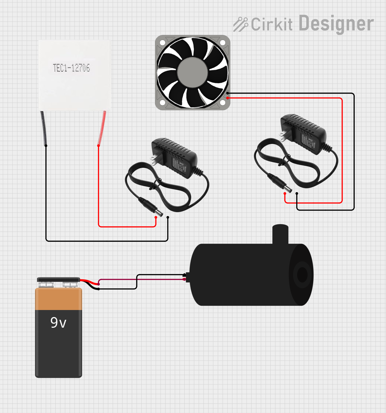
Circuit Documentation
Summary of the Circuit
The circuit described by the provided inputs consists of a Peltier module, a 40mm 12V fan, two separate 12V power supplies, a water pump, and a 9V battery. The Peltier module is used for heating or cooling applications, depending on the direction of the current flow. The 40mm fan is likely used for cooling, possibly to dissipate heat from the hot side of the Peltier module. The water pump is powered by a 9V battery and is probably used for circulating fluid in a cooling system. Each component is powered by its respective power supply, with no shared connections between the different power sources.
Component List
Peltier Module
- Description: A solid-state device that can heat or cool depending on the direction of the electrical current.
- Pins: Negative, Positive
40mm Fan 12V
- Description: A fan used for cooling, typically found in computer cases or electronic projects.
- Pins: +12V, -12V
12V Power Supply
- Description: Provides a stable 12V DC output for powering electronic components.
- Pins: +, -
Water Pump
- Description: A pump used for moving water, commonly used in cooling systems or small fountains.
- Pins: Positive, Negative
9V Battery
- Description: A standard 9V battery used for providing power to small electronic devices.
- Pins: -, +
Wiring Details
Peltier Module
- Positive: Connected to the positive output of a 12V power supply.
- Negative: Connected to the negative output of the same 12V power supply.
40mm Fan 12V
- +12V: Connected to the positive output of a 12V power supply.
- -12V: Connected to the negative output of the same 12V power supply.
Water Pump
- Positive: Connected to the positive terminal of a 9V battery.
- Negative: Connected to the negative terminal of the same 9V battery.
Documented Code
No code has been provided for any microcontrollers in the circuit. If the circuit includes programmable components or requires control logic, the relevant code will need to be developed and documented here.
This documentation provides an overview of the circuit's components and their connections. For a complete understanding, a schematic diagram and further details on the operation and control of the circuit would be necessary.