
Arduino UNO Based Health Monitoring System with MAX30100 and DHT11 Sensors
View and Edit Project In Cirkit Designer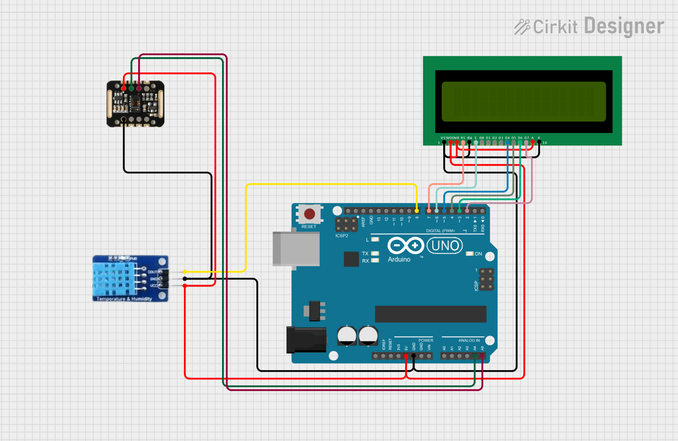
Circuit Documentation
Summary
This document provides a detailed overview of a circuit that includes an Arduino UNO microcontroller, a 16x2 LCD display, a MAX30100 pulse oximeter and heart-rate sensor, and a DHT11 temperature and humidity sensor. The circuit is designed to interface the sensors with the Arduino UNO, which processes the data and displays relevant information on the LCD. The Arduino UNO is also responsible for the control logic and communication between the components.
Component List
Arduino UNO
- Description: A microcontroller board based on the ATmega328P.
- Purpose: Acts as the central processing unit for the circuit, reading sensor data, controlling the LCD display, and executing the embedded code.
16X2 LCD
- Description: A liquid crystal display capable of displaying 16 characters per line across 2 lines.
- Purpose: To display data or messages processed by the Arduino UNO.
MAX30100
- Description: An integrated pulse oximetry and heart-rate monitor sensor module.
- Purpose: To measure the oxygen saturation level in the blood and the heart rate.
DHT11
- Description: A basic, ultra-low-cost digital temperature and humidity sensor.
- Purpose: To measure the ambient temperature and humidity.
Wiring Details
Arduino UNO
- 5V connected to:
- 16X2 LCD VDD (Power supply)
- 16X2 LCD A (Anode for backlight)
- DHT11 VCC (Power supply)
- MAX30100 VIN (Power supply)
- GND connected to:
- 16X2 LCD VSS (Ground)
- 16X2 LCD K (Cathode for backlight)
- 16X2 LCD RW (Read/Write select, typically grounded)
- DHT11 GND (Ground)
- MAX30100 GND (Ground)
- A4 (SDA) connected to MAX30100 SDA (I2C Data)
- A5 (SCL) connected to MAX30100 SCL (I2C Clock)
- D8 connected to DHT11 DATA (Data)
- D7 connected to 16X2 LCD RS (Register Select)
- D6 connected to 16X2 LCD E (Enable)
- D5 connected to 16X2 LCD D4 (Data 4)
- D4 connected to 16X2 LCD D5 (Data 5)
- D3 connected to 16X2 LCD D6 (Data 6)
- D2 connected to 16X2 LCD D7 (Data 7)
16X2 LCD
- VDD, A, V0 connected to Arduino UNO 5V
- VSS, K, RW connected to Arduino UNO GND
- RS connected to Arduino UNO D7
- E connected to Arduino UNO D6
- D4 connected to Arduino UNO D5
- D5 connected to Arduino UNO D4
- D6 connected to Arduino UNO D3
- D7 connected to Arduino UNO D2
MAX30100
- VIN connected to Arduino UNO 5V
- GND connected to Arduino UNO GND
- SDA connected to Arduino UNO A4 (SDA)
- SCL connected to Arduino UNO A5 (SCL)
DHT11
- VCC connected to Arduino UNO 5V
- GND connected to Arduino UNO GND
- DATA connected to Arduino UNO D8
Documented Code
Arduino UNO Code (sketch.ino)
void setup() {
  // put your setup code here, to run once:

}

void loop() {
  // put your main code here, to run repeatedly:

}
Additional Notes
- The provided code is a template and does not contain any functional logic. It needs to be populated with the initialization and operational code for the sensors and the LCD display.
- The
setup()function is intended for initialization code that runs once at the start, such as configuring pin modes and initializing communication protocols. - The
loop()function contains the main logic of the program, which runs repeatedly after thesetup()function completes. This is where sensor readings, data processing, and display updates should occur.