
ESP32-Based RFID and IR Sensor Interaction System with Servo Control
View and Edit Project In Cirkit Designer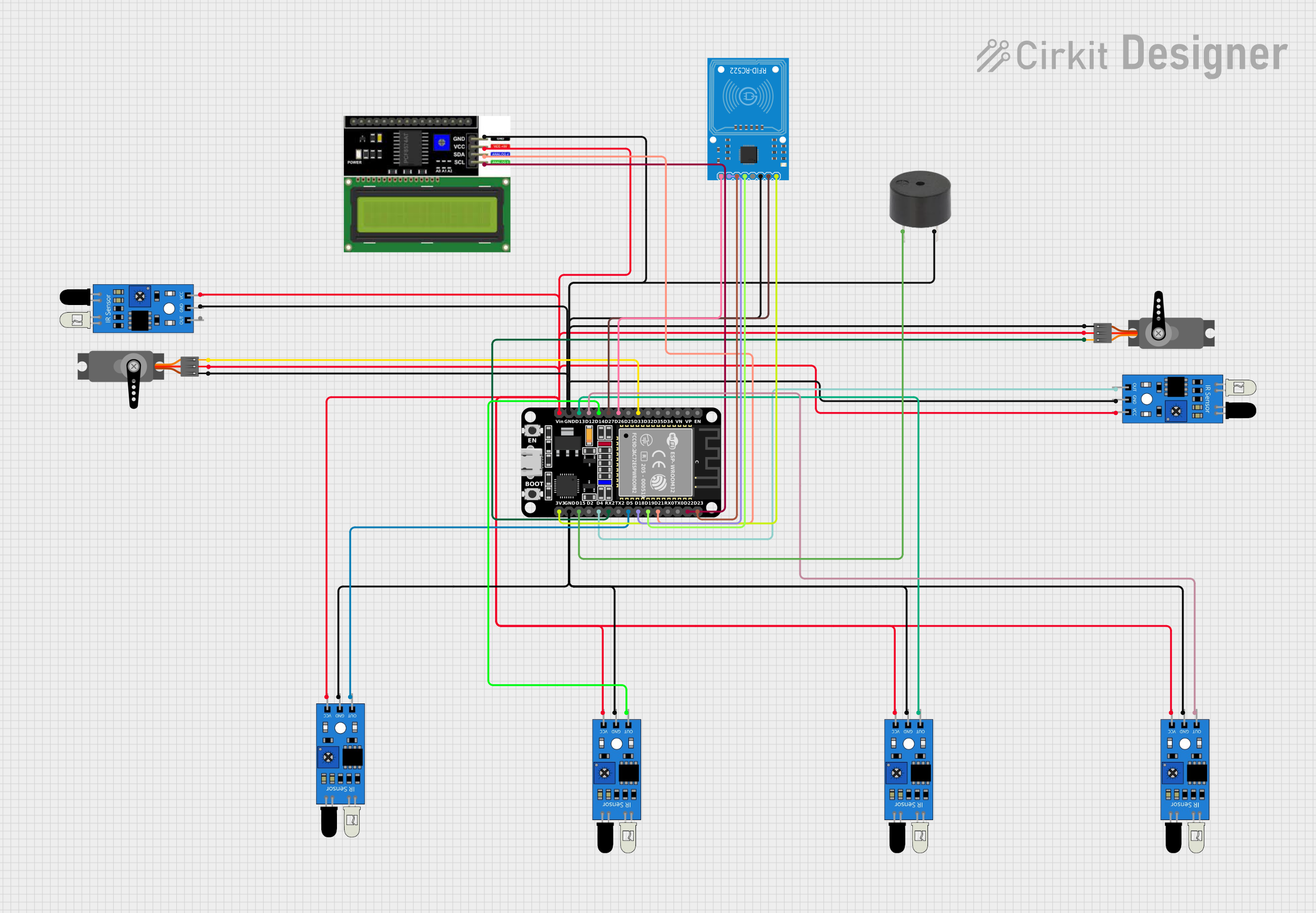
Circuit Documentation
Summary of the Circuit
This circuit is designed around the ESP32 microcontroller, which serves as the central processing unit. The circuit includes a variety of sensors and output devices, such as multiple IR sensors, an RFID-RC522 module for RFID communication, an I2C LCD display for user interface, and servo motors for actuation. Additionally, a buzzer is included for audio feedback. The ESP32 manages input from the IR sensors and the RFID module, controls the servo motors, drives the buzzer, and communicates with the LCD display.
Component List
ESP32 (30 pin)
- Description: A powerful microcontroller with Wi-Fi and Bluetooth capabilities.
- Pins: EN, VP, VN, D34, D35, D32, D33, D25, D26, D27, D14, D12, D13, GND, Vin, D23, D22, TX0, RX0, D21, D19, D18, D5, TX2, RX2, D4, D2, D15, 3V3
IR Sensor
- Description: An infrared sensor capable of detecting obstacles or measuring distances.
- Pins: out, gnd, vcc
LCD I2C Display
- Description: A liquid crystal display with an I2C interface for showing information.
- Pins: GND, VCC, SDA, SCL
RFID-RC522
- Description: An RFID reader/writer module for contactless communication.
- Pins: SDA, SCK, MOSI, MISO, IRQ, GND, RST, 3.3V
Servo
- Description: An actuator capable of precise angular positioning.
- Pins: GND, VCC, PWM
Buzzer
- Description: An electronic buzzer for producing sound signals.
- Pins: PIN, GND
Wiring Details
ESP32 (30 pin)
- D33 connected to Servo (PWM)
- D26 connected to RFID-RC522 (SDA)
- D27 connected to RFID-RC522 (RST)
- D14 connected to IR Sensor (out)
- D12 connected to IR Sensor (out)
- D13 connected to IR Sensor (out)
- GND connected to common ground net
- Vin connected to common VCC net
- D23 connected to RFID-RC522 (MOSI)
- D22 connected to LCD I2C Display (SCL)
- D21 connected to LCD I2C Display (SDA)
- D19 connected to RFID-RC522 (MISO)
- D18 connected to RFID-RC522 (SCK)
- D5 connected to IR Sensor (out)
- RX2 connected to Servo (PWM)
- D4 connected to IR Sensor (out)
- D15 connected to Buzzer (PIN)
- 3V3 connected to RFID-RC522 (3.3V)
IR Sensor
- out connected to ESP32 (various digital pins)
- gnd connected to common ground net
- vcc connected to common VCC net
LCD I2C Display
- GND connected to common ground net
- VCC connected to common VCC net
- SDA connected to ESP32 (D21)
- SCL connected to ESP32 (D22)
RFID-RC522
- SDA connected to ESP32 (D26)
- SCK connected to ESP32 (D18)
- MOSI connected to ESP32 (D23)
- MISO connected to ESP32 (D19)
- IRQ not connected
- GND connected to common ground net
- RST connected to ESP32 (D27)
- 3.3V connected to ESP32 (3V3)
Servo
- GND connected to common ground net
- VCC connected to common VCC net
- PWM connected to ESP32 (D33 or RX2)
Buzzer
- PIN connected to ESP32 (D15)
- GND connected to common ground net
Documented Code
sketch.ino
void setup() {
  // put your setup code here, to run once:

}

void loop() {
  // put your main code here, to run repeatedly:

}
documentation.txt
The code for the ESP32 microcontroller is currently empty. Further implementation is required to handle inputs from the IR sensors, communicate with the RFID module, control the servo motors, drive the buzzer, and update the LCD display.