Arduino-Controlled Robot with IR Sensors, Bluetooth, and Ultrasonic Obstacle Detection
Circuit Documentation
Summary
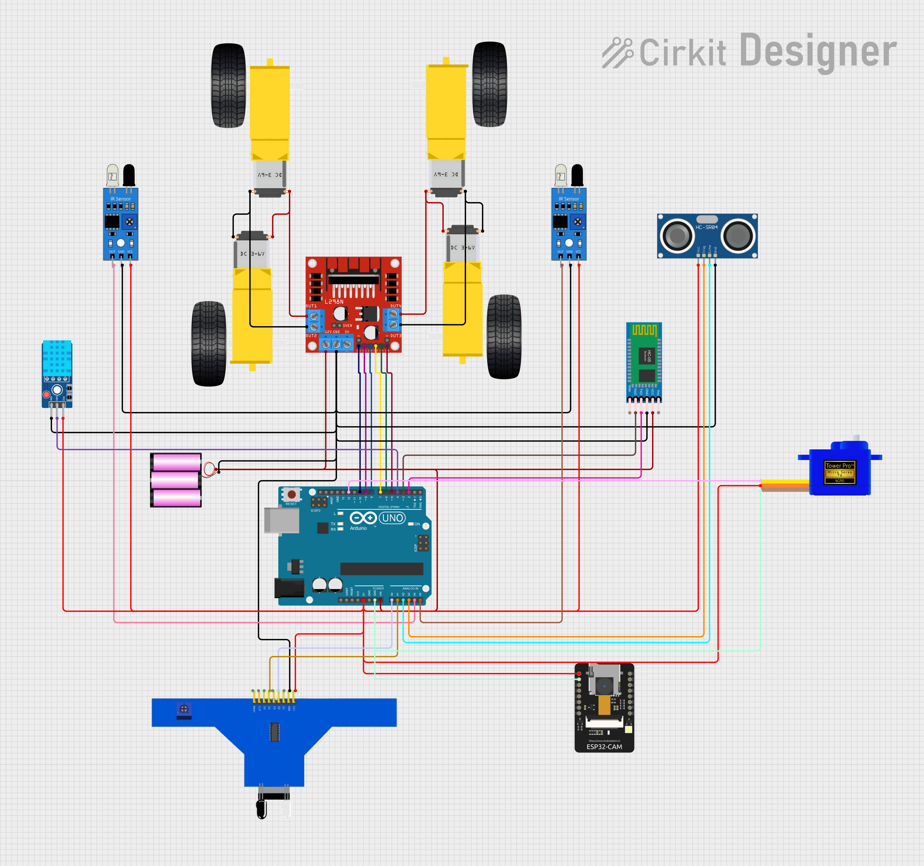
This circuit is designed to control various sensors and actuators through an Arduino UNO microcontroller. It includes motor drivers for DC gearmotors, IR sensors for object detection, a DHT11 sensor for temperature and humidity readings, an HC-05 Bluetooth module for wireless communication, an HC-SR04 ultrasonic sensor for distance measurement, an ESP32-CAM for image capture, and a servomotor for precise angular movement. The circuit is powered by a 12V battery, with voltage regulation provided for components requiring 5V.
Component List
Microcontroller
- Arduino UNO: A microcontroller board based on the ATmega328P, with digital and analog I/O pins.
Motor Driver
- L298N DC Motor Driver: A high-power motor driver capable of driving up to two DC motors.
Sensors
- IR Sensor: Used for object detection and distance measurement.
- 5 Channel IR Sensor: Provides multiple IR sensors in one package for line tracking or object detection.
- DHT11 Sensor V2: A sensor for measuring temperature and humidity.
- HC-SR04 Ultrasonic Sensor: Measures distances using ultrasonic waves.
- ESP32-CAM: A camera module with Wi-Fi capabilities for image capturing and streaming.
Actuators
- Gearmotor DC Wheels (Left and Right): DC motors with gear reduction used for driving wheels.
- Servomotor SG90: A small and lightweight servomotor for precise control of movement.
Communication Module
- HC-05 Bluetooth Module: A Bluetooth module for wireless communication.
Power Supply
- Battery 12V: Provides power to the circuit.
Wiring Details
Arduino UNO
- 5V: Powers the 5V components in the circuit.
- GND: Common ground for the circuit.
- Vin: Connected to the 12V supply for voltage input.
- A0-A5: Analog inputs connected to various sensors.
- D2-D12: Digital I/O pins used for controlling and interfacing with sensors, actuators, and communication modules.
L298N DC Motor Driver
- 12V: Power input from the 12V battery.
- GND: Ground connection.
- ENA, ENB: Enable pins for motor control, connected to Arduino digital pins.
- IN1-IN4: Input pins for motor direction control, connected to Arduino digital pins.
- OUT1-OUT4: Output pins connected to the gearmotors.
IR Sensors
- VCC: Power supply (5V).
- GND: Ground connection.
- Out: Output signal connected to Arduino analog pins.
5 Channel IR Sensor
- VCC: Power supply (5V).
- GND: Ground connection.
- S1-S5: Sensor outputs, some connected to Arduino analog pins.
DHT11 Sensor V2
- VCC: Power supply (5V).
- GND: Ground connection.
- DAT: Data pin connected to an Arduino digital pin.
HC-SR04 Ultrasonic Sensor
- VCC: Power supply (5V).
- GND: Ground connection.
- TRIG: Trigger pin connected to an Arduino digital pin.
- ECHO: Echo pin connected to an Arduino digital pin.
ESP32-CAM
- 5V: Power supply (5V).
- GND: Ground connection.
Servomotor SG90
- VCC: Power supply (5V).
- GND: Ground connection.
- SIG: Signal pin connected to an Arduino digital pin.
HC-05 Bluetooth Module
- VCC: Power supply (12V from the battery through the motor driver).
- GND: Ground connection.
- TXD: Transmit pin connected to an Arduino digital pin.
- RXD: Receive pin connected to an Arduino digital pin.
Gearmotor DC Wheels (Left and Right)
- PIN1, PIN2: Connected to the motor driver output pins.
Battery 12V
- +: Positive terminal connected to the motor driver and Arduino Vin.
- -: Negative terminal connected to the common ground.
Documented Code
void setup() {
  // put your setup code here, to run once:

}

void loop() {
  // put your main code here, to run repeatedly:

}
The provided code is a template for the Arduino UNO microcontroller. The setup() function is called once when the microcontroller is powered on or reset. It is used to initialize the pins and set the initial state of the circuit. The loop() function is called repeatedly and contains the main logic of the program. This is where the microcontroller reads sensor data, controls actuators, and communicates with other devices.
The actual implementation details are not provided in the code snippet above. The user is expected to fill in the setup and loop functions with the specific logic required for their application. This may include configuring pin modes, setting up communication protocols, reading sensor values, implementing control algorithms, and sending commands to actuators.