
Circuit Documentation
Summary
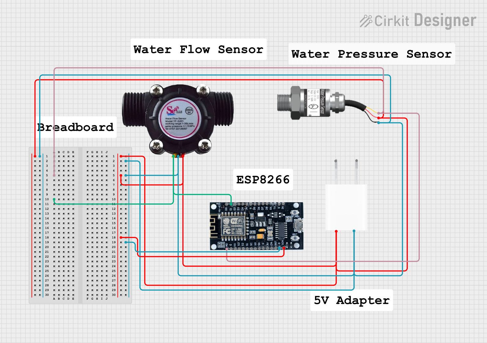
This circuit is designed to interface an ESP8266 microcontroller with a Gravity Analog Water Pressure Sensor and a water flow sensor. The circuit is powered by a 5V adapter. The ESP8266 reads the analog signal from the water pressure sensor and the digital signal from the water flow sensor. The sensors and the microcontroller share a common power supply and ground.
Component List
Gravity: Analog Water Pressure Sensor
- Description: Measures water pressure and outputs an analog signal.
- Pins: Signal, VCC, GND
5V Adapter
- Description: Provides a 5V power supply to the circuit.
- Pins: AC In 1, AC In 2, 5V, GND
ESP8266
- Description: A Wi-Fi enabled microcontroller used for reading sensor data and potentially transmitting it over a network.
- Pins: 3V, G, D8, D7, D6, D5, D4, D3, D2, D1, D0, A0, S3, S2, S1, SC, S0, SK, EN, VIN, RST, VU
Water Flow Sensor
- Description: Measures the flow rate of water and outputs a digital signal.
- Pins: Signal, Vcc, GND
Wiring Details
Gravity: Analog Water Pressure Sensor
- Signal pin is connected to A0 pin of the ESP8266.
- VCC pin is connected to 5V pin of the 5V Adapter.
- GND pin is connected to GND pin of the 5V Adapter.
5V Adapter
- 5V pin is connected to VCC pin of the Gravity: Analog Water Pressure Sensor, Vcc pin of the Water Flow Sensor, and VIN pin of the ESP8266.
- GND pin is connected to GND pin of the Gravity: Analog Water Pressure Sensor, GND pin of the Water Flow Sensor, and G pin of the ESP8266.
ESP8266
- A0 pin is connected to Signal pin of the Gravity: Analog Water Pressure Sensor.
- D1 pin is connected to Signal pin of the Water Flow Sensor.
- VIN pin is connected to 5V pin of the 5V Adapter.
- G pin is connected to GND pin of the 5V Adapter.
Water Flow Sensor
- Signal pin is connected to D1 pin of the ESP8266.
- Vcc pin is connected to 5V pin of the 5V Adapter.
- GND pin is connected to GND pin of the 5V Adapter.
Code
No code is provided for this circuit.