
Arduino UNO-Based Autonomous Obstacle-Avoiding Robot with Ultrasonic Sensor and Battery Power
View and Edit Project In Cirkit Designer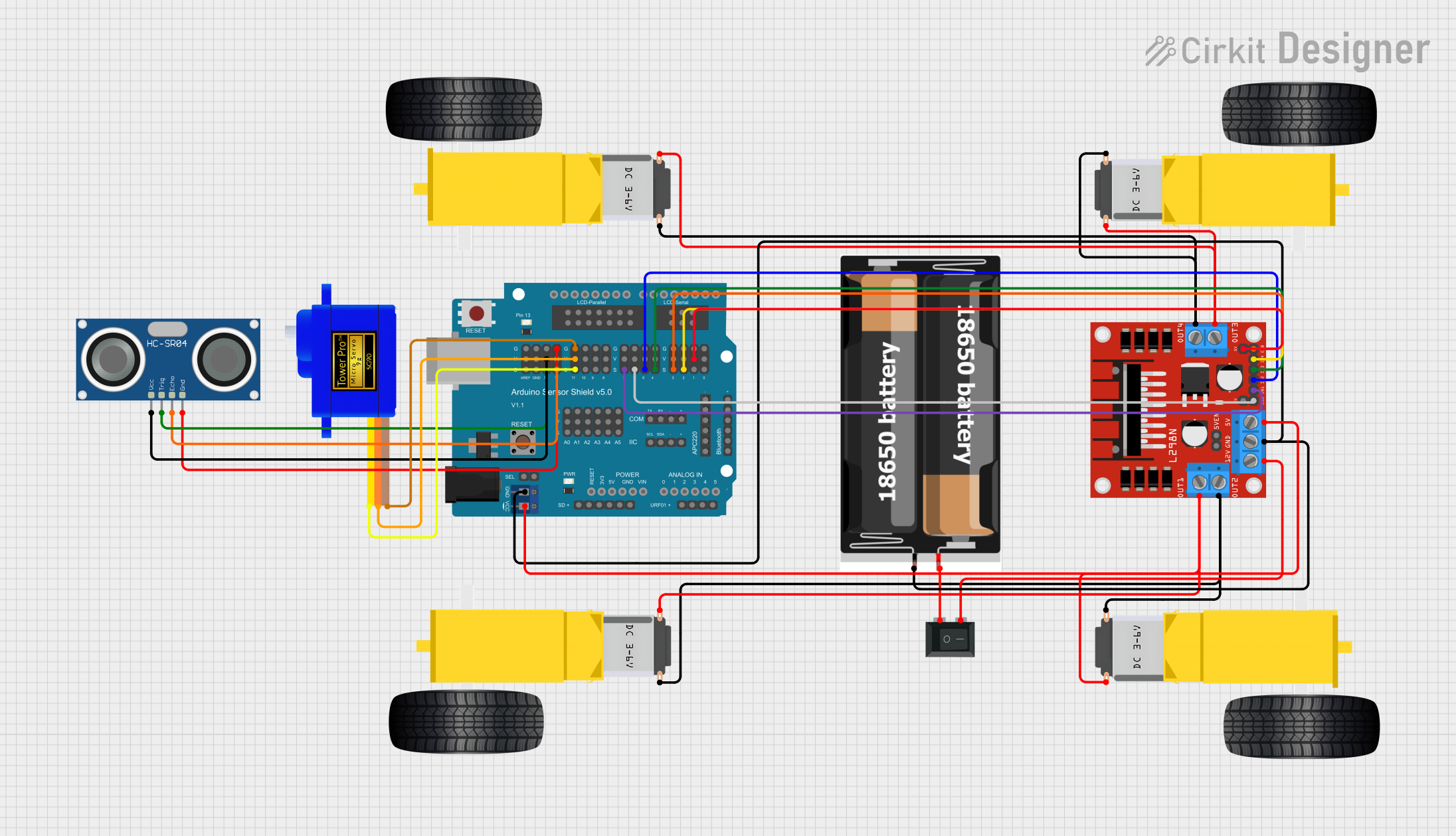
Circuit Documentation
Summary
This circuit is designed to control a robotic vehicle using an Arduino UNO microcontroller. The vehicle is equipped with an HC-SR04 Ultrasonic Sensor for distance measurement, DC gear motors for movement, a servomotor for steering, and an L298N motor driver for motor control. The circuit also includes a rocker switch for power control and a 2x 18650 battery pack for power supply. The Arduino Sensor Shield v5.0 is used to facilitate connections between the components and the Arduino UNO.
Component List
Arduino UNO
- Description: Microcontroller board based on the ATmega328P.
- Pins: UNUSED, IOREF, Reset, 3.3V, 5V, GND, Vin, A0, A1, A2, A3, A4, A5, SCL, SDA, AREF, D13, D12, D11, D10, D9, D8, D7, D6, D5, D4, D3, D2, D1, D0
HC-SR04 Ultrasonic Sensor
- Description: Ultrasonic distance sensor.
- Pins: VCC, TRIG, ECHO, GND
Gearmotor DC Wheels (Left)
- Description: DC motor for left wheels.
- Pins: PIN1, PIN2
Gearmotor DC Wheels (Right)
- Description: DC motor for right wheels.
- Pins: PIN1, PIN2
Servomotor SG90
- Description: Small servomotor for steering.
- Pins: SIG, VCC, GND
L298N DC Motor Driver
- Description: Dual H-Bridge motor driver.
- Pins: OUT1, OUT2, 12V, GND, 5V, OUT3, OUT4, 5V-ENA-JMP-I, 5V-ENA-JMP-O, +5V-J1, +5V-J2, ENA, IN1, IN2, IN3, IN4, ENB
Rocker Switch (SPST)
- Description: Single-pole single-throw switch.
- Pins: 1, 2
Arduino Sensor Shield v5.0
- Description: Shield for easy sensor connections.
- Pins: VCC, SD-VCC, SD-GND, SD-D11, SD-D10, SD-D13, SD-D12, URF01-VCC, URF01-A0, URF01-A1, URF01-GND, GND, SEL1, SEL2, A0-SIG, A0-VCC, A0-GND, A1-SIG, A1-VCC, A1-GND, A2-SIG, A2-VCC, A2-GND, A3-SIG, A3-VCC, A3-GND, A4-SIG, A4-VCC, A4-GND, A5-SIG, A5-VCC, A5-GND, IIC-SCL, IIC-SDA, IIC-GND, IIC-VCC, COM-TX, COM-RX, COM-GND, COM-VCC, APC220-, APC220-D0, APC220-D1, APC220-VCC, APC220-GND, BLUETOOTH-3V3, BLUETOOTH-GND, BLUETOOTH-D0, BLUETOOTH-D1, BLUETOOTH-VCC, AREF-S, AREF-V, AREF-G, GND-S, GND-V, GND-G, 13-S, 13-V, 13-G, 12-S, 12-V, 12-G, 11-S, 11-V, 11-G, 10-S, 10-V, 10-G, 9-S, 9-V, 9-G, 8-S, 8-V, 8-G, 7-S, 7-V, 7-G, 6-S, 6-V, 6-G, 5-S, 5-V, 5-G, 4-S, 4-V, 4-G, 3-S, 3-V, 3-G, 2-S, 2-V, 2-G, 1-S, 1-V, 1-G, 0-S, 0-V, 0-G, ParallelLCD-VCC, ParallelLCD-D13, ParallelLCD-GND, ParallelLCD-D12, ParallelLCD-D2, ParallelLCD-D11, ParallelLCD-D3, ParallelLCD-D10, ParallelLCD-D4, ParallelLCD-D9, ParallelLCD-D5, ParallelLCD-D8, ParallelLCD-D6, ParallelLCD-D7, SerialLCD-D4, SerialLCD-VCC, SerialLCD-D3, SerialLCD-, SerialLCD-D2, SerialLCD-GND
2x 18650 Battery Pack
- Description: Battery pack with two 18650 cells.
- Pins: vcc, gnd
Wiring Details
Arduino UNO
- Connected to the Arduino Sensor Shield v5.0 for all pin connections.
HC-SR04 Ultrasonic Sensor
- VCC: Connected to Arduino Sensor Shield v5.0 pin 13-V
- TRIG: Connected to Arduino Sensor Shield v5.0 pin 13-S
- ECHO: Connected to Arduino Sensor Shield v5.0 pin 12-S
- GND: Connected to Arduino Sensor Shield v5.0 pin 12-G
Gearmotor DC Wheels (Left)
- PIN1: Connected to L298N DC motor driver pin OUT2
- PIN2: Connected to L298N DC motor driver pin OUT1
Gearmotor DC Wheels (Right)
- PIN1: Connected to L298N DC motor driver pin OUT4
- PIN2: Connected to L298N DC motor driver pin OUT3
Servomotor SG90
- SIG: Connected to Arduino Sensor Shield v5.0 pin 11-S
- VCC: Connected to Arduino Sensor Shield v5.0 pin 11-V
- GND: Connected to Arduino Sensor Shield v5.0 pin 11-G
L298N DC Motor Driver
- OUT1: Connected to Gearmotor DC Wheels (Left) pin PIN2
- OUT2: Connected to Gearmotor DC Wheels (Left) pin PIN1
- OUT3: Connected to Gearmotor DC Wheels (Right) pin PIN2
- OUT4: Connected to Gearmotor DC Wheels (Right) pin PIN1
- 12V: Connected to Rocker Switch (SPST) pin 2
- GND: Connected to Arduino Sensor Shield v5.0 pin GND and 2x 18650 pin gnd
- 5V: Connected to Arduino Sensor Shield v5.0 pin VCC
- +5V-J2: Connected to Arduino Sensor Shield v5.0 pin 1-V
- ENA: Connected to Arduino Sensor Shield v5.0 pin 6-S
- IN1: Connected to Arduino Sensor Shield v5.0 pin 7-S
- IN2: Connected to Arduino Sensor Shield v5.0 pin 5-S
- IN3: Connected to Arduino Sensor Shield v5.0 pin 4-S
- IN4: Connected to Arduino Sensor Shield v5.0 pin 2-S
- ENB: Connected to Arduino Sensor Shield v5.0 pin 3-S
Rocker Switch (SPST)
- 1: Connected to 2x 18650 pin vcc
- 2: Connected to L298N DC motor driver pin 12V
Arduino Sensor Shield v5.0
- GND: Connected to L298N DC motor driver pin GND and 2x 18650 pin gnd
- VCC: Connected to L298N DC motor driver pin 5V
- 1-V: Connected to L298N DC motor driver pin +5V-J2
- 6-S: Connected to L298N DC motor driver pin ENA
- 7-S: Connected to L298N DC motor driver pin IN1
- 5-S: Connected to L298N DC motor driver pin IN2
- 4-S: Connected to L298N DC motor driver pin IN3
- 2-S: Connected to L298N DC motor driver pin IN4
- 3-S: Connected to L298N DC motor driver pin ENB
- 13-V: Connected to HC-SR04 Ultrasonic Sensor pin VCC
- 13-S: Connected to HC-SR04 Ultrasonic Sensor pin TRIG
- 12-S: Connected to HC-SR04 Ultrasonic Sensor pin ECHO
- 12-G: Connected to HC-SR04 Ultrasonic Sensor pin GND
- 11-S: Connected to Servomotor SG90 pin SIG
- 11-V: Connected to Servomotor SG90 pin VCC
- 11-G: Connected to Servomotor SG90 pin GND