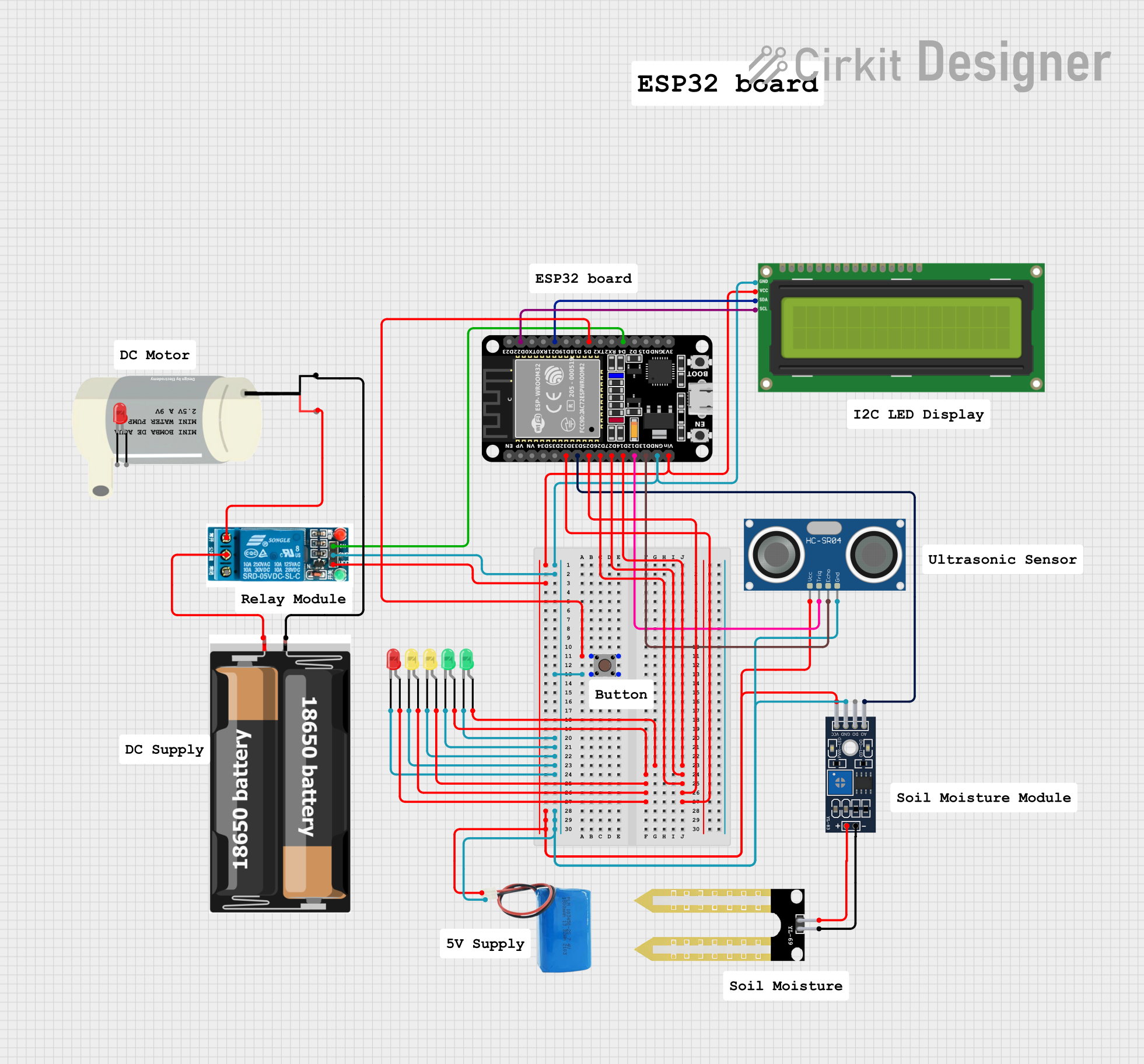
ESP32-Based Automated Plant Watering System with Soil Moisture Monitoring and LCD Feedback

Circuit Documentation
Summary
This circuit integrates various components controlled by an ESP32 microcontroller to perform a range of functions. The ESP32 is connected to input devices, output devices, and sensors, including a pushbutton, an I2C LCD screen, a relay module, an ultrasonic sensor, a soil moisture sensor module, a mini water pump, and multiple LEDs. The circuit is powered by a 5V battery and a 2x 18650 battery pack. The ESP32 reads inputs from the pushbutton and sensors to control the relay, which in turn controls the water pump, and to display information on the LCD screen. LEDs are used as status indicators.
Component List
- ESP32 (30 pin): A microcontroller with WiFi and Bluetooth capabilities, featuring a variety of digital I/O pins.
- 5V Relay: An electromechanical switch that allows the ESP32 to control higher power devices like the mini water pump.
- I2C LCD 16x2 Screen: A display screen for showing text information, interfaced with the ESP32 via the I2C protocol.
- YL-69 Sonda: A soil moisture sensor probe.
- YL-83 Module LM393: A comparator module that interfaces with the YL-69 Sonda to provide digital and analog soil moisture readings.
- Mini Water Pump: An electric pump controlled by the relay to pump water when activated.
- Pushbutton: A simple switch that provides input to the ESP32.
- HC-SR04 Ultrasonic Sensor: A sensor that measures distance using ultrasonic waves.
- 2x 18650 Battery Pack: A power source for the circuit.
- 5V Battery: An additional power source for the circuit.
- LEDs (Red, Green, Yellow): Light-emitting diodes used as visual indicators.
Wiring Details
ESP32 (30 pin)
D5: Connected to the pushbutton.GND: Common ground for the circuit.Vin: Connected to the VCC of the I2C LCD screen, 5V relay, and HC-SR04 ultrasonic sensor.D14,D27,D26,D25,D32: Connected to the anodes of various LEDs.D33: Connected to the A0 pin of the YL-83 Module LM393.D12: Connected to the TRIG pin of the HC-SR04 Ultrasonic Sensor.D13: Connected to the ECHO pin of the HC-SR04 Ultrasonic Sensor.D22: Connected to the SCL pin of the I2C LCD screen.D21: Connected to the SDA pin of the I2C LCD screen.D4: Connected to the In pin of the 5V relay.
5V Relay
GND: Connected to the common ground.VCC: Connected to the 5V battery positive terminal.In: Controlled by the ESP32 to switch the relay.Normally Open: Connected to the VCC of the mini water pump.Common terminal: Connected to the VCC of the 2x 18650 battery pack.
I2C LCD 16x2 Screen
SCL: Connected to the D22 pin of the ESP32.SDA: Connected to the D21 pin of the ESP32.VCC (5V): Powered by the Vin pin of the ESP32.GND: Connected to the common ground.
YL-69 Sonda and YL-83 Module LM393
+and-: Interconnected between the YL-69 Sonda and YL-83 Module LM393.A0: The analog output from the YL-83 Module LM393 to the D33 pin of the ESP32.GND: Connected to the common ground.VCC: Powered by the 5V battery positive terminal.
Mini Water Pump
VCC: Powered by the Normally Open terminal of the 5V relay.GND: Connected to the GND of the 2x 18650 battery pack.
Pushbutton
Pin 1 (in)andPin 2 (in): Connected to the D5 pin of the ESP32.Pin 3 (out)andPin 4 (out): Connected to the common ground.
HC-SR04 Ultrasonic Sensor
VCC: Powered by the Vin pin of the ESP32.TRIG: Connected to the D12 pin of the ESP32.ECHO: Connected to the D13 pin of the ESP32.GND: Connected to the common ground.
2x 18650 Battery Pack
vcc: Connected to the Common terminal of the 5V relay.gnd: Connected to the GND of the mini water pump.
5V Battery
positive: Connected to the VCC of the I2C LCD screen, 5V relay, and HC-SR04 ultrasonic sensor.negative: Connected to the common ground.
LEDs (Red, Green, Yellow)
cathode: Connected to the common ground.anode: Connected to various GPIO pins on the ESP32 for status indication.
Documented Code
sketch.ino
void setup() {
  // put your setup code here, to run once:

}

void loop() {
  // put your main code here, to run repeatedly:

}
documentation.txt
The code for the ESP32 microcontroller is currently a template with empty setup() and loop() functions. The setup() function is intended to initialize the pins and peripherals, while the loop() function will contain the main logic for reading sensors, controlling the relay, updating the LCD display, and managing LED states. The actual implementation will depend on the specific requirements of the circuit's operation.