
Arduino Uno-Based Automated Motor Control System with Rain Sensor and Relay
View and Edit Project In Cirkit Designer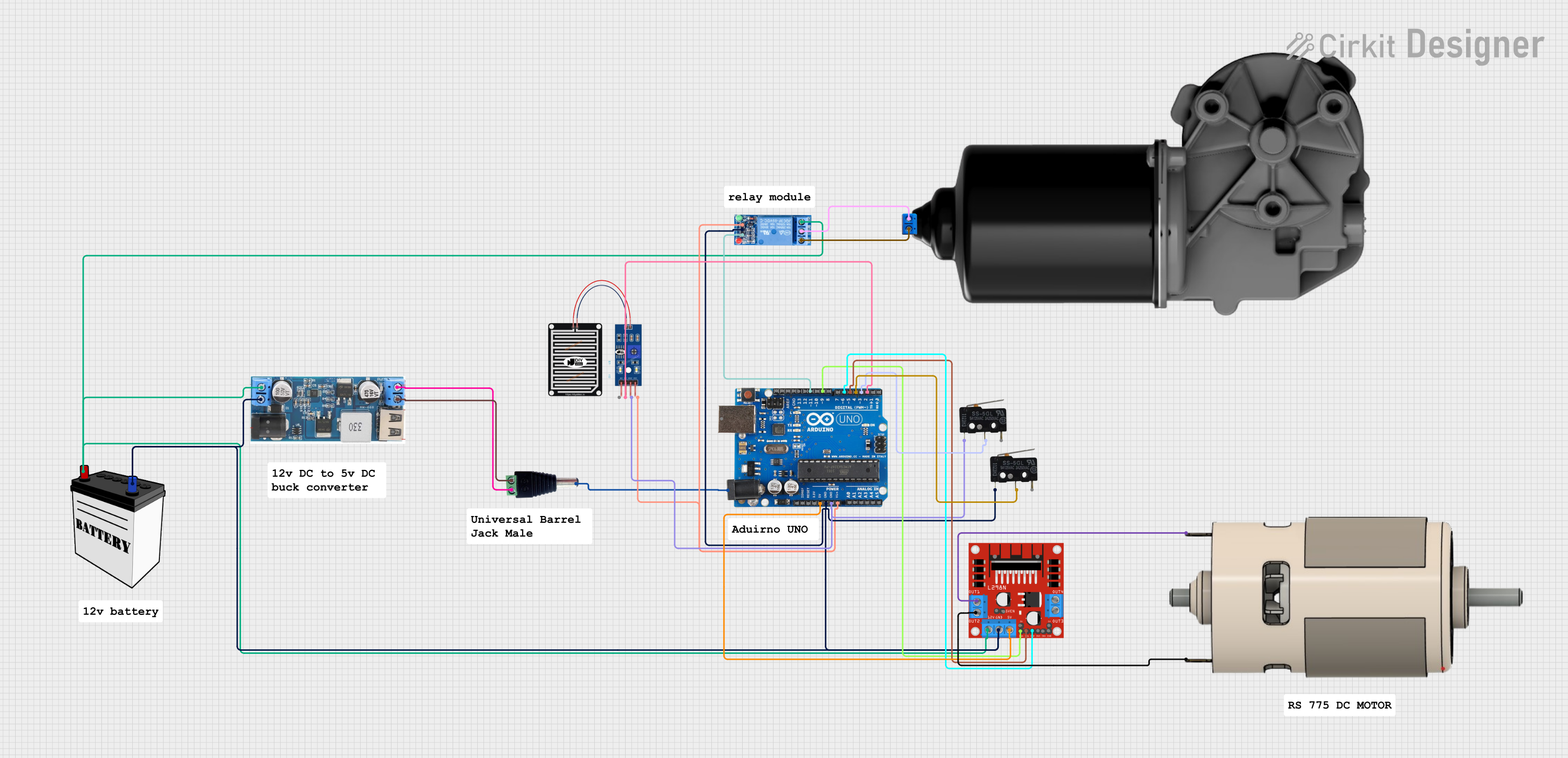
Circuit Documentation
Summary
This document provides a detailed overview of a circuit that includes an Arduino Uno R3, a 1 Channel Relay, a 12V Battery, a Universal Barrel Jack Male, a DCDC 12V/5V converter, an L298N DC motor driver, a Rain Sensor, Micro Switches, an RS 775 DC Motor, a DC Worm Gear Motor, and a Terminal PCB. The circuit is designed to control motors and respond to environmental conditions such as rain.
Component List
Arduino Uno R3
- Description: A microcontroller board based on the ATmega328P.
- Pins: D8, D9, D10, D11, D12, D13, GND, AREF, SDA, SCL, D0/RX, D1/Tx, D2, D3, D4, D5, 6, D7, A5/SCL, A4/SDA, A3, A2, A1, A0, Vin, 5V, 3.3V, RESET, IOREF, NONE, USB Jack, Power Jack
1 Channel Relay 5V
- Description: A relay module that allows control of high voltage devices.
- Pins: VCC, GND, IN, NC, COM, NO
12V Battery
- Description: A power source providing 12V.
- Pins: VCC, GND
Universal Barrel Jack Male
- Description: A connector for providing power to the circuit.
- Pins: Power Out, V+, V-
DCDC 12V/5V 3A
- Description: A DC-DC converter that steps down 12V to 5V.
- Pins: 12V (+), GND, 5V (+), Vin (+), V in (-)
L298N DC Motor Driver
- Description: A dual H-Bridge motor driver.
- Pins: OUT1, OUT2, 12V, GND, 5V, OUT3, OUT4, 5V-ENA-JMP-I, 5V-ENA-JMP-O, +5V-J1, +5V-J2, ENA, IN1, IN2, IN3, IN4, ENB
Rain Sensor
- Description: A sensor module to detect rain.
- Pins: AO, DO, GRD, VCC
Micro Switch
- Description: A small switch used for detecting physical interactions.
- Pins: COM, NO, NC
RS 775 DC Motor
- Description: A high-power DC motor.
- Pins: V+, V-
DC Worm Gear Motor
- Description: A motor with a worm gear for high torque applications.
- Pins: Motor+, Motor-
Terminal PCB 2 Pin
- Description: A terminal block for connecting wires.
- Pins: Pin A, Pin B
Wiring Details
Arduino Uno R3
- D9 connected to L298N DC motor driver ENA
- D11 connected to 1 Channel Relay 5V IN
- D2 connected to Rain Sensor DO
- D3 connected to Micro Switch NO
- D4 connected to Micro Switch NO
- D5 connected to L298N DC motor driver IN1
- 6 connected to L298N DC motor driver IN2
- Vin connected to Rain Sensor VCC and 1 Channel Relay 5V VCC
- GND connected to Micro Switch COM, Rain Sensor GRD, DCDC 12V/5V 3A V in (-), 12V Battery GND, L298N DC motor driver GND, 1 Channel Relay 5V GND, Micro Switch COM
- 5V connected to L298N DC motor driver 5V
- Power Jack connected to Universal Barrel Jack Male Power Out
1 Channel Relay 5V
- IN connected to Arduino Uno R3 D11
- VCC connected to Arduino Uno R3 Vin
- GND connected to Arduino Uno R3 GND
- NC connected to Terminal PCB 2 Pin Pin B
- COM connected to Terminal PCB 2 Pin Pin A
- NO connected to DCDC 12V/5V 3A Vin (+)
12V Battery
- VCC connected to DCDC 12V/5V 3A Vin (+)
- GND connected to DCDC 12V/5V 3A V in (-)
Universal Barrel Jack Male
- Power Out connected to Arduino Uno R3 Power Jack
- V+ connected to DCDC 12V/5V 3A 5V (+)
- V- connected to DCDC 12V/5V 3A GND
DCDC 12V/5V 3A
- V in (-) connected to Arduino Uno R3 GND
- Vin (+) connected to 12V Battery VCC
- 5V (+) connected to Universal Barrel Jack Male V+
- GND connected to Universal Barrel Jack Male V-
L298N DC Motor Driver
- ENA connected to Arduino Uno R3 D9
- IN1 connected to Arduino Uno R3 D5
- IN2 connected to Arduino Uno R3 6
- 12V connected to DCDC 12V/5V 3A Vin (+)
- GND connected to DCDC 12V/5V 3A V in (-)
- 5V connected to Arduino Uno R3 5V
- OUT1 connected to RS 775 DC Motor V+
- OUT2 connected to RS 775 DC Motor V-
Rain Sensor
- DO connected to Arduino Uno R3 D2
- VCC connected to Arduino Uno R3 Vin
- GRD connected to Arduino Uno R3 GND
Micro Switch
- NO connected to Arduino Uno R3 D3
- COM connected to Arduino Uno R3 GND
RS 775 DC Motor
- V+ connected to L298N DC motor driver OUT1
- V- connected to L298N DC motor driver OUT2
Terminal PCB 2 Pin
- Pin A connected to 1 Channel Relay 5V COM
- Pin B connected to 1 Channel Relay 5V NC
Documented Code
Arduino Uno R3 Code
const int relayPin = 11;  // Relay control pin

void setup() {
  pinMode(relayPin, OUTPUT);
}

void loop() {
  // Turn the motor ON for 2 seconds
  digitalWrite(relayPin, HIGH);
  delay(2000);
  // Turn the motor OFF for 10 seconds
  digitalWrite(relayPin, LOW);
  delay(10000);
}
1 Channel Relay 5V Code
void setup() {
  // put your setup code here, to run once:
}

void loop() {
  // put your main code here, to run repeatedly:
}
This document provides a comprehensive overview of the circuit, including the components used, their connections, and the code running on the microcontrollers.