Arduino and ESP32-CAM Based GPS Tracker
Circuit Documentation
Summary
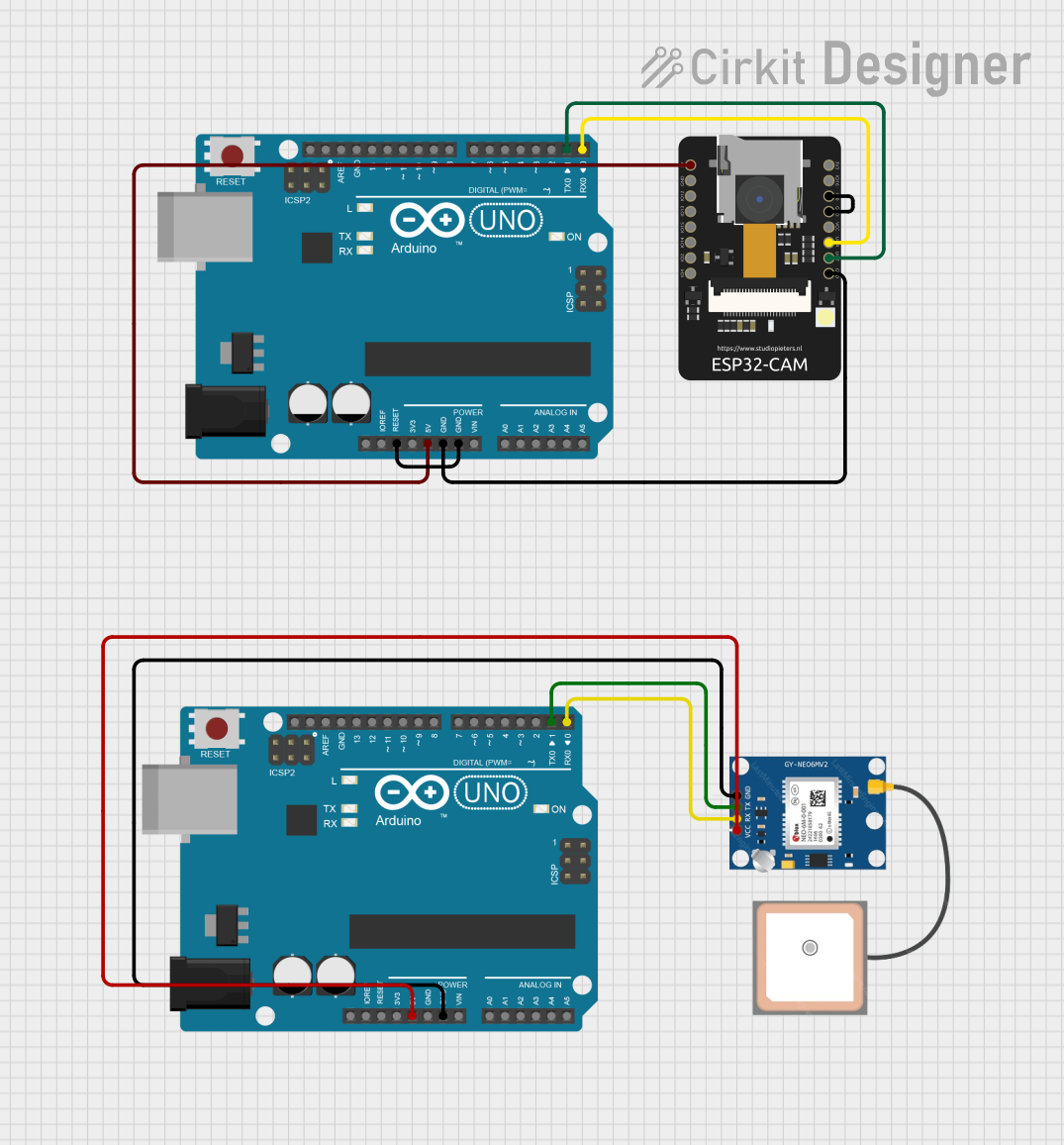
This circuit integrates an Arduino UNO, an ESP32-CAM module, and a GPS NEO 6M module. The Arduino UNO serves as the primary microcontroller, while the ESP32-CAM provides camera functionality and Wi-Fi/Bluetooth capabilities. The GPS NEO 6M module is used for obtaining geographical location data. The circuit is designed to capture images and possibly transmit them along with location data, which could be used in applications such as remote monitoring or asset tracking.
Component List
Arduino UNO
- Microcontroller board based on the ATmega328P
- Digital I/O Pins: 14 (of which 6 provide PWM output)
- Analog Input Pins: 6
- Operating Voltage: 5V
- Features: 16 MHz quartz crystal, USB connection, power jack, ICSP header, and a reset button
ESP32 - CAM
- Wi-Fi and Bluetooth module with an integrated camera
- Operating Voltage: 5V
- Features: Multiple GPIOs, supports OV2640 and OV7670 cameras, supports image Wi-FI upload
GPS NEO 6M
- GPS module with ceramic antenna
- Operating Voltage: 3.3V to 5V
- Features: UART interface, 6M with onboard EEPROM
Wiring Details
Arduino UNO
5Vconnected to ESP32-CAM5Vand GPS NEO 6MVCCGNDconnected to ESP32-CAMGNDand GPS NEO 6MGNDD0connected to ESP32-CAMVORD1connected to ESP32-CAMVOTResetconnected toGND(Note: This connection is unusual and might be an error in the net list)
ESP32 - CAM
5Vconnected to Arduino UNO5VGNDconnected to Arduino UNOGNDand ESP32-CAMIO0VOTconnected to Arduino UNOD1VORconnected to Arduino UNOD0
GPS NEO 6M
VCCconnected to Arduino UNO5VRXconnected to Arduino UNOD0TXconnected to Arduino UNOD1GNDconnected to Arduino UNOGND
Documented Code
Arduino UNO (Primary Controller)
void setup() {
  // put your setup code here, to run once:

}

void loop() {
  // put your main code here, to run repeatedly:

}
Arduino UNO (Secondary Controller)
void setup() {
  // put your setup code here, to run once:

}

void loop() {
  // put your main code here, to run repeatedly:

}
(Note: The provided code for both Arduino UNO controllers is a template with no specific functionality. The actual application code needs to be developed based on the requirements of the project.)
This documentation provides an overview of the circuit's components, their connections, and the initial code templates for the microcontrollers. Further development and detailed code documentation are required to fulfill the circuit's intended purpose.