
Raspberry Pi 3B Temperature Monitoring and Fan Control System
View and Edit Project In Cirkit Designer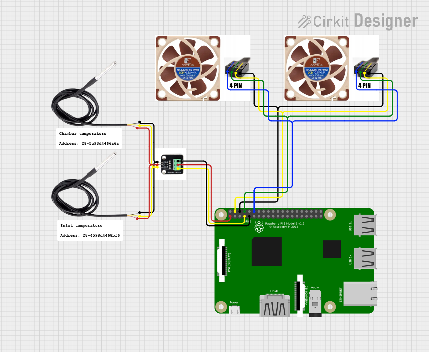
Circuit Documentation
Summary
This circuit involves a Raspberry Pi 3B, two Noctua 40mm NF-A4x20 5V PWM 5000RPM Fans, a DS18B20 Adapter, and two DS18B20 temperature sensors. The Raspberry Pi serves as the central control unit, interfacing with the fans and temperature sensors to monitor and control the environment.
Component List
Raspberry Pi 3B
- Description: A single-board computer used for various applications.
- Pins: 1, 3, 5, 7, 9, 11, 13, 15, 17, 21, 23, 25, 27, 29, 33, 37, 39, 40, 38, 36, 34, 32, 30, 26, 24, 22, 20, 18, 16, 14, 12, 10, 8, 6, 4, 2(5V), 19, 28, 31, 35
Noctua 40mm NF-A4x20 5V PWM 5000RPM Fan
- Description: A 40mm fan with PWM control for speed regulation.
- Pins: GND, +5V, RPM Signal, PWM Signal
DS18B20 Adapter
- Description: An adapter for the DS18B20 temperature sensor.
- Pins: DAT, VCC, GND
DS18B20
- Description: A digital temperature sensor.
- Pins: signal, GND, vcc
Wiring Details
Raspberry Pi 3B
- Pin 1: Connected to VCC of DS18B20 Adapter
- Pin 7: Connected to DAT of DS18B20 Adapter
- Pin 9: Connected to GND of DS18B20 Adapter
- Pin 12: Connected to PWM Signal of both Noctua Fans
- Pin 8: Connected to RPM Signal of both Noctua Fans
- Pin 6: Connected to GND of both Noctua Fans
- Pin 4: Connected to +5V of both Noctua Fans
Noctua 40mm NF-A4x20 5V PWM 5000RPM Fan
- GND: Connected to Pin 6 of Raspberry Pi
- +5V: Connected to Pin 4 of Raspberry Pi
- RPM Signal: Connected to Pin 8 of Raspberry Pi
- PWM Signal: Connected to Pin 12 of Raspberry Pi
DS18B20 Adapter
- DAT: Connected to Pin 7 of Raspberry Pi and signal of both DS18B20 sensors
- VCC: Connected to Pin 1 of Raspberry Pi and vcc of both DS18B20 sensors
- GND: Connected to Pin 9 of Raspberry Pi and GND of both DS18B20 sensors
DS18B20
- signal: Connected to DAT of DS18B20 Adapter
- GND: Connected to GND of DS18B20 Adapter
- vcc: Connected to VCC of DS18B20 Adapter
Code
No code is provided for this circuit.