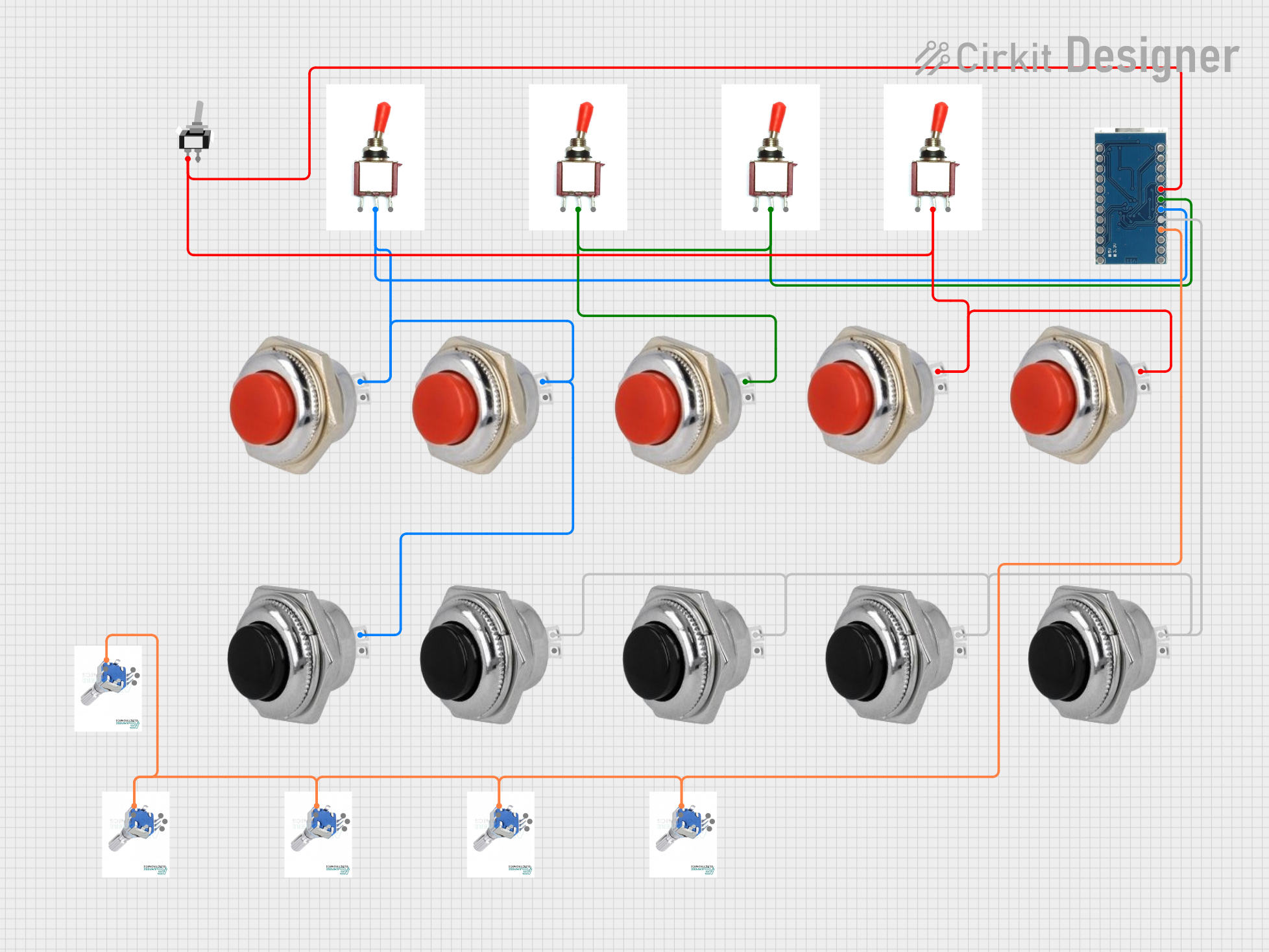
Arduino-Controlled Input Interface with Momentary Switches and Rotary Encoders

Circuit Documentation
Summary
The circuit in question is designed to interface a series of momentary switches, toggle switches, and rotary encoders with an Arduino Micro Pro microcontroller. The momentary switches are divided into two groups: red and black, each with two pins labeled "In" and "Out". The toggle switches have three pins labeled "Vcc", "Sig", and "Gnd". The rotary encoders have four pins labeled "GND", "Out A", "Out B", and "Switch". The Arduino Micro Pro serves as the central processing unit for the circuit, with multiple digital input pins connected to the various switches and encoders to detect user interactions.
Component List
Momentary Switches
- Red Momentary Switch 32 mm: A push-button switch that momentarily closes the circuit when pressed.
- Black Momentary Switch 32 mm: Similar to the red switch, but in black for possible functional or aesthetic differentiation.
Toggle Switches
- Toggle Switch: A switch with three positions that can connect and disconnect circuits in various configurations.
Rotary Encoders
- EC11 Rotary Encoder: An input device that provides rotational position feedback and includes a push-button switch.
Microcontroller
- Arduino Micro Pro: A small-sized microcontroller board based on the ATmega32U4, with various digital and analog I/O pins.
Special Purpose Switches
- Toggle Switch SPST: A single-pole single-throw toggle switch with two positions, open and closed.
Wiring Details
Red Momentary Switches
- Pin "In": Connected to the signal pin of a toggle switch or directly to a digital input pin on the Arduino Micro Pro.
- Pin "Out": Typically connected to ground or a pull-up resistor network.
Black Momentary Switches
- Pin "In": Connected to the signal pin of a toggle switch or directly to a digital input pin on the Arduino Micro Pro.
- Pin "Out": Typically connected to ground or a pull-up resistor network.
Toggle Switches
- Pin "Vcc": Connected to the power supply voltage.
- Pin "Sig": Connected to the input pin of a momentary switch or directly to a digital input pin on the Arduino Micro Pro.
- Pin "Gnd": Connected to the ground.
Rotary Encoders
- Pin "GND": Connected to the ground.
- Pin "Out A" and "Out B": Connected to two digital input pins on the Arduino Micro Pro for position feedback.
- Pin "Switch": Connected to a digital input pin on the Arduino Micro Pro to detect push-button activation.
Arduino Micro Pro
- Digital Input Pins: Connected to the "In" pins of momentary switches, "Sig" pins of toggle switches, and "Switch" pins of rotary encoders.
Toggle Switch SPST
- Pin "L1": Connected to the input pin of a momentary switch or directly to a digital input pin on the Arduino Micro Pro.
- Pin "COM": Common pin, typically connected to the power supply or ground.
Documented Code
No code has been provided for the microcontroller. The expected code would involve setting up the digital input pins to read the state of the switches and encoders, debouncing the inputs, and implementing any required logic to respond to user interactions.
When code is available, it should be documented here with explanations for each function and significant lines of code. The documentation should also include information on how to compile and upload the code to the Arduino Micro Pro.