Cirkit Designer
Your all-in-one circuit design IDE
Home /
Project Documentation
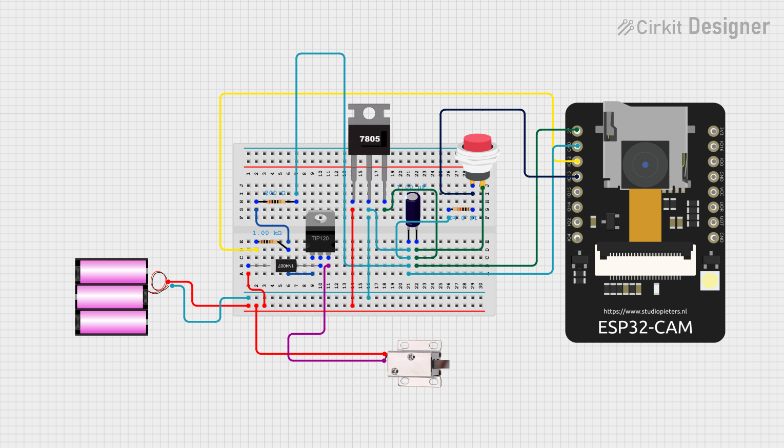
ESP32 CAM Controlled Solenoid Lock System

Circuit Documentation
Summary
The circuit in question appears to be a control system utilizing an ESP32 CAM microcontroller to potentially manage a 12V solenoid lock, with power regulation and switching capabilities. The circuit includes a voltage regulator (7805) to provide a stable 5V output, a rectifier diode for protection, resistors for current limiting and pull-up/pull-down functions, a Darlington transistor for high-current switching, an electrolytic capacitor for voltage smoothing, a push switch for user input, and a 12V battery as the power source.
Component List
Resistor
- Description: Passive electrical component providing resistance to current flow.
- Properties:
- 1k Ohm
- 200 Ohm
- 10k Ohm
Electrolytic Capacitor
- Description: Polarized capacitor with a larger capacitance per unit volume.
- Properties:
- 1 µF
TIP120 Hi-Current Darlington Transistor
- Description: A transistor capable of handling high current loads.
- Properties:
- N/A
7805 Voltage Regulator
- Description: A voltage regulator that outputs a stable 5V from a higher voltage input.
- Properties:
- N/A
2Pin Push Switch
- Description: A simple switch that connects or disconnects the circuit.
- Properties:
- N/A
1N4007 Rectifier Diode
- Description: A diode commonly used for rectifying voltages, capable of withstanding high reverse voltage.
- Properties:
- N/A
12V Solenoid Lock
- Description: An electromagnetic lock that operates on 12V.
- Properties:
- N/A
ESP32 CAM
- Description: A microcontroller with integrated Wi-Fi and camera capabilities.
- Properties:
- N/A
Battery 12V
- Description: A 12V power source for the circuit.
- Properties:
- N/A
Wiring Details
Resistor (1k Ohm)
- Connected to ESP32 CAM (GPIO12)
Resistor (200 Ohm)
- Connected between TIP120 (BASE) and Resistor (1k Ohm)
Resistor (10k Ohm)
- Connected to 2Pin Push Switch (Input +)
- Connected to ESP32 CAM (GPIO13)
Electrolytic Capacitor (1 µF)
- Negative side connected to 7805 (Gnd)
- Positive side connected to 7805 (Vout)
TIP120 Hi-Current Darlington Transistor
- BASE connected to Resistor (1k Ohm)
- EMITTER connected to 12V Solenoid Lock (GND)
- COLLECTOR connected to 1N4007 Rectifier Diode (Anode)
7805 Voltage Regulator
- Vin connected to 1N4007 Rectifier Diode (Cathode) and Battery 12V (+)
- Gnd connected to Electrolytic Capacitor (-) and ESP32 CAM (GND)
- Vout connected to Electrolytic Capacitor (+) and ESP32 CAM (5V)
2Pin Push Switch
- Input + connected to Resistor (10k Ohm)
- Output + connected to ESP32 CAM (5V)
1N4007 Rectifier Diode
- Cathode connected to 7805 (Vin) and Battery 12V (+)
- Anode connected to TIP120 (COLLECTOR)
12V Solenoid Lock
- VCC connected to Battery 12V (+)
- GND connected to TIP120 (EMITTER)
ESP32 CAM
- 5V connected to 7805 (Vout)
- GND connected to 7805 (Gnd)
- GPIO12 connected to Resistor (1k Ohm)
- GPIO13 connected to Resistor (10k Ohm)
Battery 12V
- connected to 7805 (Vin) and 1N4007 Rectifier Diode (Cathode)
- connected to ESP32 CAM (GND)
Documented Code
ESP32 CAM Code (sketch.ino)
void setup() {
  // put your setup code here, to run once:

}

void loop() {
  // put your main code here, to run repeatedly:

}
Additional Notes (documentation.txt)
No additional code documentation provided.