Cirkit Designer
Your all-in-one circuit design IDE
Home /
Project Documentation
ESP32-Based Water Flow Monitoring System with OLED Display

Circuit Documentation
Summary
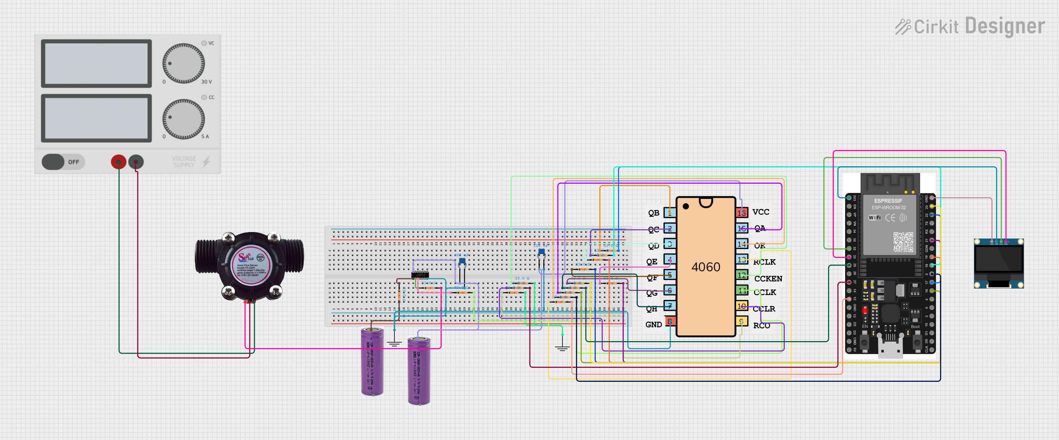
This circuit appears to be designed for sensing water flow and displaying data on an OLED screen, with the core processing handled by an ESP32 microcontroller. The circuit includes a water flow sensor, a 0.96" OLED display, a 4060 binary counter, a level shifter (SN74AHCT125N), power supply components, and various resistors and capacitors for signal conditioning and power stabilization.
Component List
Integrated Circuits
- 4060 Binary Counter: A 14-stage ripple-carry binary counter/divider and oscillator.
- SN74AHCT125N Level Shifter: A quadruple bus buffer gate with 3-state outputs.
- ESP32 38 PINS: A microcontroller with Wi-Fi and Bluetooth capabilities, featuring a wide variety of GPIOs.
Sensors
- Water Flow Sensor: A device that measures the flow rate of water passing through it.
Displays
- 0.96" OLED: A small display for visual output.
Power Supply Components
- Power Supply: Provides a stable voltage source for the circuit.
- 3.3v Batteries: Two batteries to supply power to various components.
Passive Components
- Resistors: Multiple resistors, all with a resistance of 33 Ohms, used for various purposes in the circuit.
- Ceramic Capacitors: Two capacitors with a capacitance of 0.1 µF, likely used for noise suppression and power stabilization.
Connectors
- GND: Ground reference points for the circuit.
Wiring Details
4060 Binary Counter
- Pin 16 connected to 3.3v battery (+)
- Pin 8 connected to GND
- Pins 1, 2, 3, 4, 5, 6, 7, 9, 10, 11, 12, 13, 14, 15 connected to various resistors
Water Flow Sensor
- Signal pin connected to a resistor
- Vcc pin connected to Power Supply (+)
- GND pin connected to Power Supply (-)
SN74AHCT125N Level Shifter
- 1OE pin connected to a resistor and 3.3v battery (+)
- 1A pin connected to a resistor
- 1Y pin connected to a resistor
- Vcc pin connected to 3.3v battery (+) and Ceramic Capacitors
- GND pin connected to GND and Ceramic Capacitors
ESP32 38 PINS
- Various GPIOs connected to resistors
- GND pin connected to OLED GND and GND reference
- 3V3 pin connected to OLED VDD
- Pins 32, 33 connected to OLED SCK, SDA respectively
0.96" OLED
- GND pin connected to ESP32 GND
- VDD pin connected to ESP32 3V3
- SCK pin connected to ESP32 GPIO 32
- SDA pin connected to ESP32 GPIO 33
Power Supply
- (+) pin connected to Water Flow Sensor Vcc
- (-) pin connected to Water Flow Sensor GND
3.3v Batteries
- (+) pins connected to 4060 Pin 16 and SN74AHCT125N Vcc
- (-) pins are not explicitly connected in the provided net list
Resistors
- All resistors are 33 Ohms and are connected between various components and pins as detailed in the net list.
Ceramic Capacitors
- Both capacitors are 0.1 µF and are connected between the SN74AHCT125N Vcc/GND and the 3.3v battery (+)/GND.
Documented Code
No code was provided for the microcontroller or any other programmable components in the circuit. Therefore, this section is not applicable for the current documentation.