
Circuit Documentation
Summary
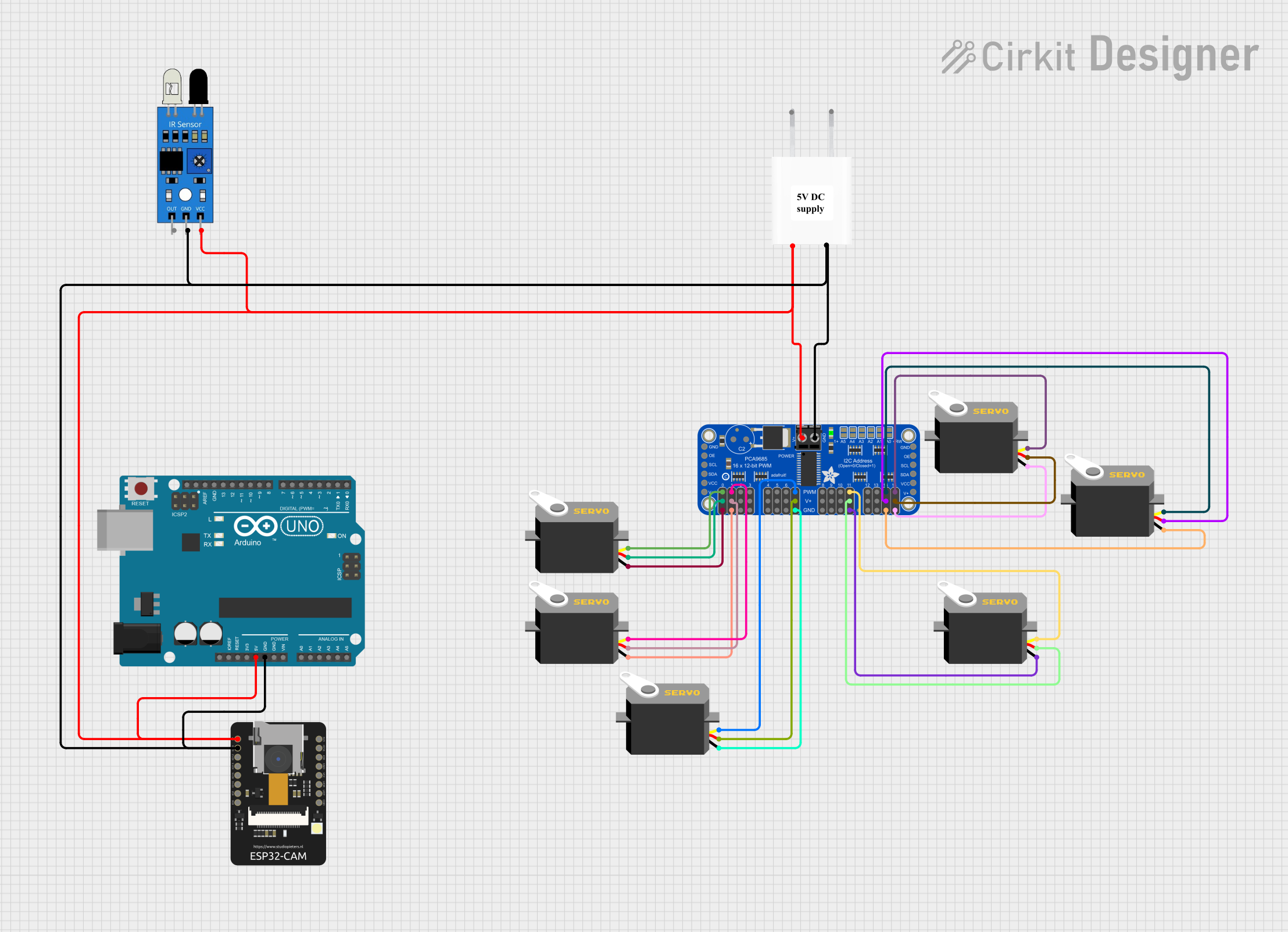
This circuit involves the use of multiple servos controlled by an Adafruit PCA9685 PWM Servo Breakout, an ESP32-CAM for wireless communication, an Arduino UNO for central control, and an IR sensor for object detection. The circuit is powered by a 5V adapter.
Component List
Servo
- Description: A standard servo motor.
- Pins: gnd, vcc, pulse
Adafruit PCA9685 PWM Servo Breakout
- Description: A PWM driver board used to control multiple servos.
- Pins: 5.0V, GND, PWRIN, PWM0-PWM15, VCC, SDA, SCL, OE
ESP32 - CAM
- Description: A microcontroller with built-in Wi-Fi and camera capabilities.
- Pins: 5V, GND, IO12, IO13, IO15, IO14, IO2, IO4, VOT, VOR, VCC, IO0, IO16, 3V3
Arduino UNO
- Description: A microcontroller board based on the ATmega328P.
- Pins: UNUSED, IOREF, Reset, 3.3V, 5V, GND, Vin, A0-A5, SCL, SDA, AREF, D0-D13
5V Adapter
- Description: A power adapter providing 5V output.
- Pins: AC In 1, AC In 2, 5V, GND
IR Sensor
- Description: An infrared sensor for object detection.
- Pins: out, gnd, vcc
Wiring Details
Servo
- Ground (gnd): Connected to GND on Adafruit PCA9685 PWM Servo Breakout.
- Power (vcc): Connected to 5.0V on Adafruit PCA9685 PWM Servo Breakout.
- Pulse (pulse): Connected to PWM pins (PWM0, PWM1, PWM7, PWM15, PWM11, PWM14) on Adafruit PCA9685 PWM Servo Breakout.
Adafruit PCA9685 PWM Servo Breakout
- 5.0V: Connected to vcc of all servos.
- GND: Connected to gnd of all servos.
- PWRIN: Connected to 5V on 5V Adapter, Arduino UNO, ESP32-CAM, and IR Sensor.
- PWM0: Connected to pulse of Servo.
- PWM1: Connected to pulse of Servo.
- PWM7: Connected to pulse of Servo.
- PWM15: Connected to pulse of Servo.
- PWM11: Connected to pulse of Servo.
- PWM14: Connected to pulse of Servo.
ESP32 - CAM
- 5V: Connected to PWRIN on Adafruit PCA9685 PWM Servo Breakout.
- GND: Connected to GND on Adafruit PCA9685 PWM Servo Breakout.
Arduino UNO
- 5V: Connected to PWRIN on Adafruit PCA9685 PWM Servo Breakout.
- GND: Connected to GND on Adafruit PCA9685 PWM Servo Breakout.
5V Adapter
- 5V: Connected to PWRIN on Adafruit PCA9685 PWM Servo Breakout.
- GND: Connected to GND on Adafruit PCA9685 PWM Servo Breakout.
IR Sensor
- vcc: Connected to PWRIN on Adafruit PCA9685 PWM Servo Breakout.
- gnd: Connected to GND on Adafruit PCA9685 PWM Servo Breakout.
Documented Code
Arduino UNO Code
void setup() {
  // put your setup code here, to run once:

}

void loop() {
  // put your main code here, to run repeatedly:

}
Additional Documentation
// No additional documentation provided.
This documentation provides a comprehensive overview of the circuit, including a summary, detailed component list, wiring details, and documented code.