Arduino UNO-Based Smart Irrigation System with Soil Moisture and Water Level Sensors
Circuit Documentation
Summary
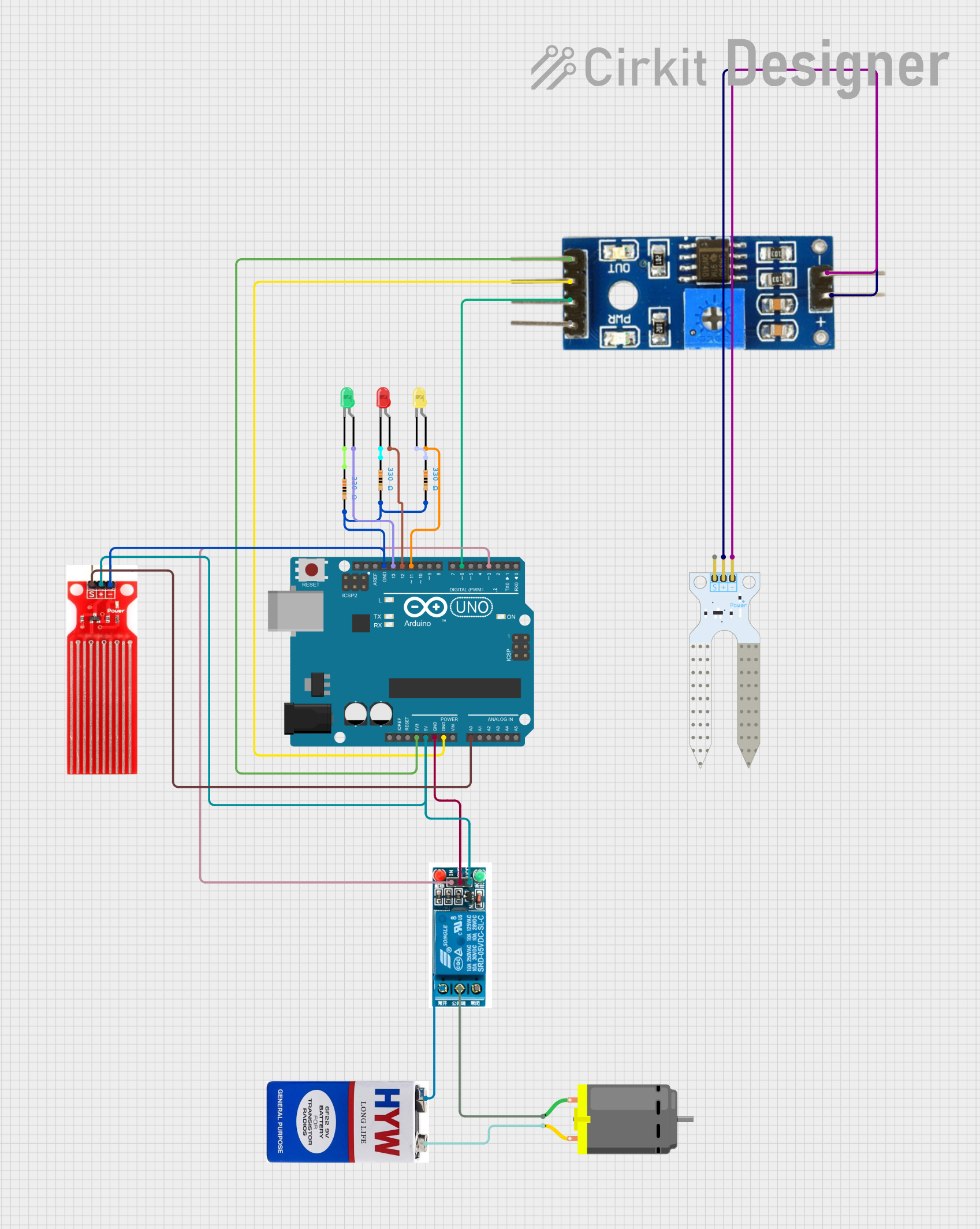
This circuit is designed to monitor soil moisture levels and control a water pump using a relay. It also provides visual feedback using LEDs to indicate the moisture level. The circuit uses an Arduino UNO as the main microcontroller, interfacing with a soil moisture sensor, a water sensor, a relay, a DC motor (acting as a water pump), and three LEDs (green, yellow, and red) to indicate different moisture levels.
Component List
Arduino UNO
- Description: Microcontroller board based on the ATmega328P.
- Pins: UNUSED, IOREF, Reset, 3.3V, 5V, GND, Vin, A0, A1, A2, A3, A4, A5, SCL, SDA, AREF, D13, D12, D11, D10, D9, D8, D7, D6, D5, D4, D3, D2, D1, D0
Soil Moisture Sensor
- Description: Sensor to measure the moisture level in the soil.
- Pins: VCC, GND, SIG
Soil Moisture Module
- Description: Module to interface with the soil moisture sensor.
- Pins: positive, negative, Analog, Digital, Ground, VCC
5V Relay
- Description: Relay module to control high voltage devices.
- Pins: Normally Open, Common terminal, Normally Closed, In, GND, VCC
9V Battery
- Description: Power source for the DC motor.
- Pins: +, -
DC Motor
- Description: Motor to act as a water pump.
- Pins: pin 1, pin 2
Water Sensor
- Description: Sensor to detect the presence of water.
- Pins: Signal, VCC, GND
LED: Two Pin (red)
- Description: Red LED for visual indication.
- Pins: cathode, anode
LED: Two Pin (green)
- Description: Green LED for visual indication.
- Pins: cathode, anode
LED: Two Pin (yellow)
- Description: Yellow LED for visual indication.
- Pins: cathode, anode
Resistor (330 Ohms)
- Description: Resistor to limit current through LEDs.
- Pins: pin1, pin2
Wiring Details
Arduino UNO
- 3.3V: Connected to VCC of Soil Moisture Module.
- 5V: Connected to VCC of Water Sensor and VCC of 5V Relay.
- GND: Connected to GND of 5V Relay, Ground of Soil Moisture Module, and GND of Water Sensor.
- A0: Connected to Signal of Water Sensor.
- D13: Connected to anode of Green LED.
- D12: Connected to anode of Red LED.
- D11: Connected to anode of Yellow LED.
- D6: Connected to Digital of Soil Moisture Module.
- D3: Connected to In of 5V Relay.
Soil Moisture Sensor
- VCC: Connected to positive of Soil Moisture Module.
- GND: Connected to negative of Soil Moisture Module.
Soil Moisture Module
- VCC: Connected to 3.3V of Arduino UNO.
- Ground: Connected to GND of Arduino UNO.
- Digital: Connected to D6 of Arduino UNO.
- positive: Connected to VCC of Soil Moisture Sensor.
- negative: Connected to GND of Soil Moisture Sensor.
5V Relay
- VCC: Connected to 5V of Arduino UNO.
- GND: Connected to GND of Arduino UNO.
- In: Connected to D3 of Arduino UNO.
- Normally Open: Connected to + of 9V Battery.
- Common terminal: Connected to pin 1 of DC Motor.
9V Battery
- +: Connected to Normally Open of 5V Relay.
- -: Connected to pin 2 of DC Motor.
DC Motor
- pin 1: Connected to Common terminal of 5V Relay.
- pin 2: Connected to - of 9V Battery.
Water Sensor
- Signal: Connected to A0 of Arduino UNO.
- VCC: Connected to 5V of Arduino UNO.
- GND: Connected to GND of Arduino UNO.
LED: Two Pin (red)
- anode: Connected to D12 of Arduino UNO.
- cathode: Connected to pin1 of Resistor.
LED: Two Pin (green)
- anode: Connected to D13 of Arduino UNO.
- cathode: Connected to pin1 of Resistor.
LED: Two Pin (yellow)
- anode: Connected to D11 of Arduino UNO.
- cathode: Connected to pin1 of Resistor.
Resistor (330 Ohms)
- pin1: Connected to cathode of respective LEDs.
- pin2: Connected to GND of Arduino UNO.
Documented Code
int water; //random variable
int value;

void setup() {
  pinMode(3, OUTPUT); //output pin for relay board, this will send signal to the relay
  pinMode(6, INPUT); //input pin coming from soil sensor
  pinMode(A0, INPUT);
  pinMode(13, OUTPUT);
  pinMode(12, OUTPUT);
  pinMode(11, OUTPUT);
}

void loop() {
  water = digitalRead(6);  // reading the coming signal from the soil sensor
  if(water == HIGH) // if water level is full then cut the relay
  {
    digitalWrite(3, LOW); // low is to cut the relay
  }
  else
  {
    digitalWrite(3, HIGH); //high to continue providing signal and water supply
  }
  delay(400);
  value = analogRead(A0);
  if(value <= 300)
  {
    digitalWrite(13, 1); // Green
    digitalWrite(12, 0); // Yellow
    digitalWrite(11, 0); // Red
  }
  else if(value <= 400)
  {
    digitalWrite(13, 0); // Green
    digitalWrite(12, 1); // Yellow
    digitalWrite(11, 0); // Red
  }
  else
  {
    digitalWrite(13, 0); // Green
    digitalWrite(12, 0); // Yellow
    digitalWrite(11, 1); // Red
  }
}
This code initializes the pins for the relay, soil sensor, and LEDs. In the loop, it reads the soil moisture level and controls the relay accordingly. It also reads the water sensor value and lights up the appropriate LED based on the moisture level.