
ESP32C3-Controlled Dual RGB LED Strip with Pushbutton Interaction
View and Edit Project In Cirkit Designer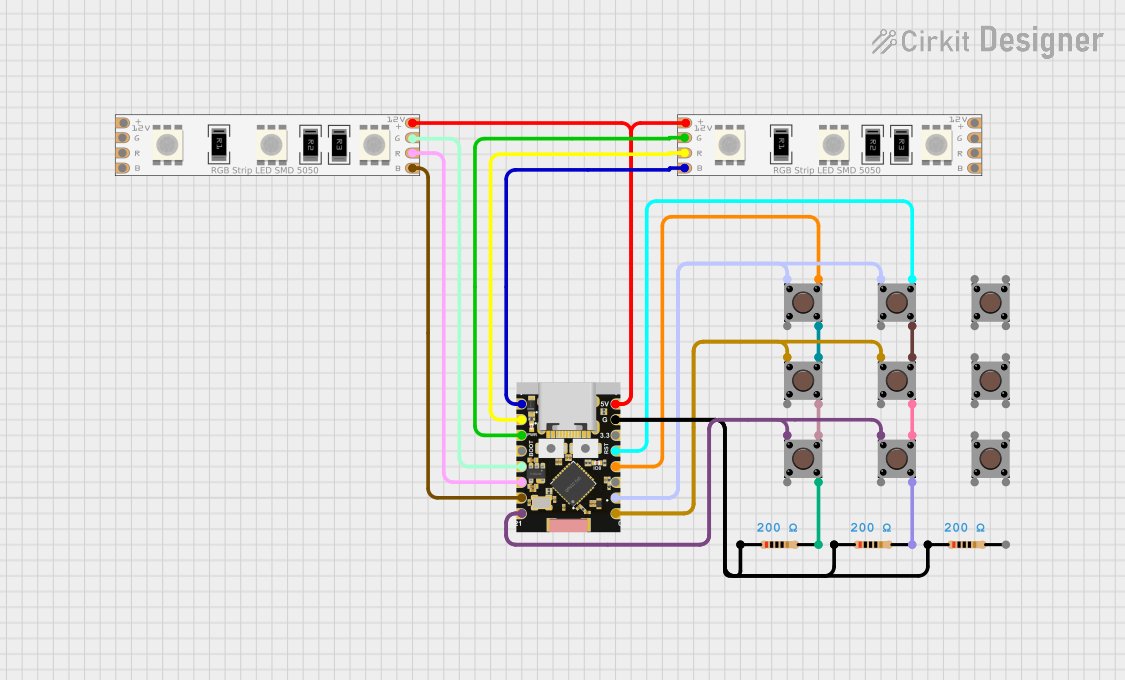
Circuit Documentation
Summary
The circuit in question appears to be designed to control an RGB LED strip using an ESP32C3 Supermini microcontroller. The circuit includes multiple pushbuttons and resistors that likely serve as input devices and current-limiting elements, respectively. The RGB LED strip is connected to the microcontroller, which can control the color and brightness of the LEDs. The pushbuttons may be used to change the LED patterns or colors. The resistors are likely used for pull-up or pull-down configurations for the pushbuttons.
Component List
LED RGB Strip
- Description: An RGB LED strip capable of displaying multiple colors.
- Pins: Common Connect, Blue Connect, Red Connect, Green Connect.
Resistor
- Description: A passive two-terminal electrical component that implements electrical resistance as a circuit element.
- Properties: 200 Ohms resistance.
Pushbutton
- Description: A simple switch mechanism for controlling some aspect of a machine or a process.
- Pins: Pin 3 (out), Pin 4 (out), Pin 1 (in), Pin 2 (in).
ESP32C3 Supermini
- Description: A small form-factor system on a chip that integrates Wi-Fi and Bluetooth capabilities and is commonly used for IoT projects.
- Pins: GPIO05, GPIO06, GPIO07, GPIO08, GPIO09, GPIO10, GPIO20, GPIO21, GPIO00, GPIO01, GPIO02, GPIO03, GPIO04, 3.3V, GND, +5V.
Wiring Details
LED RGB Strip
- Common Connect: Connected to +5V on the ESP32C3 Supermini.
- Blue Connect: Connected to GPIO20 (first strip) and GPIO05 (second strip) on the ESP32C3 Supermini.
- Red Connect: Connected to GPIO10 (first strip) and GPIO06 (second strip) on the ESP32C3 Supermini.
- Green Connect: Connected to GPIO09 (first strip) and GPIO07 (second strip) on the ESP32C3 Supermini.
Resistor
- Pin1: Connected to GND on the ESP32C3 Supermini.
- Pin2: Connected to Pin 4 (out) on various Pushbuttons.
Pushbutton
- Pin 3 (out): Connected to various GPIO pins on the ESP32C3 Supermini and other Pushbuttons.
- Pin 4 (out): Connected to Pin2 on various Resistors and other Pushbuttons.
- Pin 1 (in): Connected to various GPIO pins on the ESP32C3 Supermini and other Pushbuttons.
- Pin 2 (in): Not connected in the provided net list.
ESP32C3 Supermini
- GPIO Pins: Connected to corresponding pins on the LED RGB Strips and Pushbuttons as detailed above.
- 3.3V: Not connected in the provided net list.
- GND: Connected to Pin1 on various Resistors.
- +5V: Connected to Common Connect on both LED RGB Strips.
Documented Code
No code was provided in the input. Typically, this section would include the embedded code for the microcontroller, including initialization routines, control logic for the RGB LED strip, and debounce logic for the pushbuttons. The code would also include comments explaining the functionality of each part of the program. Since no code is available, this section remains empty.