Cirkit Designer
Your all-in-one circuit design IDE
Home /
Project Documentation
Arduino-Controlled 74HC595 Shift Register LED Driver
Circuit Documentation
Summary
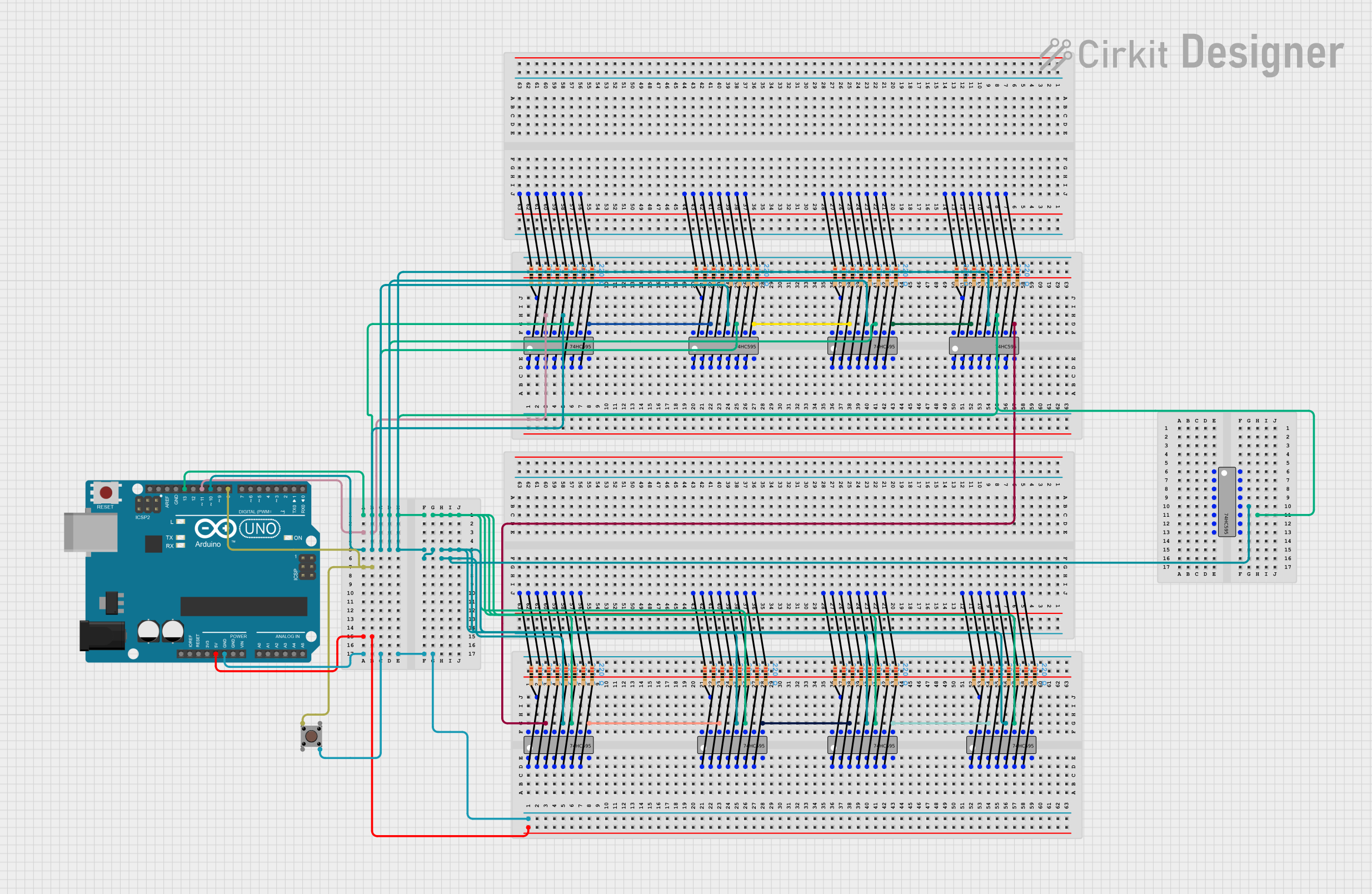
This circuit utilizes multiple 74HC595 shift registers to expand the number of digital outputs available from an Arduino UNO microcontroller. The shift registers are daisy-chained to allow for serial data input from the Arduino, which then controls multiple outputs. Each output of the shift registers is connected to a resistor, likely for current limiting purposes, which suggests that the outputs may be driving LEDs or similar devices. A pushbutton is also included in the circuit, interfaced directly with the Arduino.
Component List
Microcontroller
- Arduino UNO: A microcontroller board based on the ATmega328P, featuring digital and analog I/O pins.
Shift Registers
- 74HC595: A series of 8-bit serial-in, parallel-out shift registers, which are used to increase the number of digital outputs from the Arduino UNO.
Resistors
- 220 Ohm Resistors: These resistors are used to limit current, possibly for protecting LEDs or other sensitive components connected to the outputs of the shift registers.
Pushbutton
- Pushbutton: A simple pushbutton switch used to provide input to the Arduino UNO.
Wiring Details
Arduino UNO
- Digital Pin 11 (D11) is connected to the DS (DATA) input of the first 74HC595 shift register.
- Digital Pin 10 (D10) is connected to the ST_CP (RCLK) input of all 74HC595 shift registers.
- Digital Pin 13 (D13) is connected to the SH_CP (SRCLK) input of all 74HC595 shift registers.
- Digital Pin 8 (D8) is connected to one side of the pushbutton.
- The 5V and GND pins provide power to the circuit.
74HC595 Shift Registers
- The DS (DATA) input of each shift register (except the first) is connected to the Q7' (QH) output of the preceding shift register, creating a daisy chain configuration.
- The ST_CP (RCLK) and SH_CP (SRCLK) inputs of all shift registers are connected in parallel to the corresponding pins on the Arduino UNO.
- Each Q0-Q7 output of the shift registers is connected to a 220 Ohm resistor.
220 Ohm Resistors
- One side of each resistor is connected to an output pin (Q0-Q7) of a 74HC595 shift register.
- The other side of each resistor is left unconnected in this documentation, but it is assumed to connect to an LED or other component not listed in the provided details.
Pushbutton
- One side of the pushbutton is connected to the D8 pin on the Arduino UNO.
- The other side of the pushbutton is connected to GND.
Documented Code
Arduino UNO Code (sketch.ino)
void setup() {
  // put your setup code here, to run once:

}

void loop() {
  // put your main code here, to run repeatedly:

}
Additional Notes (documentation.txt)
No additional code documentation was provided.