ESP8266 WiFi-Controlled LED Lighting System
Circuit Documentation
Summary
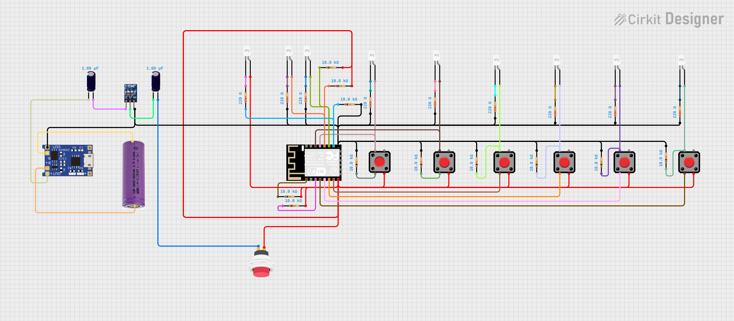
This circuit is designed around the ESP8266 ESP-12F WiFi Module, which serves as the central processing unit with WiFi capabilities. The circuit includes multiple pushbuttons and LEDs, indicating a user interface for input and visual feedback. The resistors are used for current limiting and pull-up/down configurations. The AMS1117 3.3V voltage regulator is used to ensure a stable power supply for the ESP8266 module. A TP4056 charging module is included for battery management, and electrolytic capacitors are used for voltage smoothing. The 3.3V battery provides the power source for the circuit.
Component List
Microcontroller
- ESP8266 ESP-12F WiFi Module: A microcontroller module with integrated WiFi, multiple GPIOs, and ADC capabilities.
Input Components
- Pushbuttons: Momentary switches used for user input.
- 2Pin Push Switch: A switch used to control power flow in the circuit.
Output Components
- LEDs (white): Light Emitting Diodes used as visual indicators.
Passive Components
- Resistors: Various resistors used for current limiting and pull-up/down configurations. The resistances used are 220 Ohms and 10,000 Ohms.
- Electrolytic Capacitors: Capacitors with a capacitance of 1 microfarad used for voltage smoothing.
Power Management
- AMS1117 3.3: A voltage regulator that provides a stable 3.3V output from a higher voltage input.
- 3.3V Battery: The power source for the circuit.
- TP4056: A charging module for managing the battery charging process.
Wiring Details
ESP8266 ESP-12F WiFi Module
- GND: Connected to the ground plane and various components for a common reference point.
- GPIO15: Connected to a 10k Ohm resistor.
- GPIO2: Connected to an LED (anode) and a 10k Ohm resistor.
- GPIO0: Connected to an LED (anode) and a 10k Ohm resistor.
- GPIO4: Connected to a pushbutton and an LED (anode).
- GPIO5: Connected to an LED (anode) and a pushbutton.
- RST: Connected to a 10k Ohm resistor.
- EN: Connected to a 10k Ohm resistor.
- GPIO16: Connected to a pushbutton.
- GPIO14: Connected to a pushbutton.
- GPIO12: Connected to a pushbutton.
- GPIO13: Connected to a pushbutton.
- VCC: Connected to various pushbuttons, a 2Pin Push Switch, and LEDs through resistors.
Pushbuttons
- Pin 1/Pin 3: Connected to the VCC or GPIOs of the ESP8266 module.
- Pin 2: Connected to GPIOs of the ESP8266 module.
- Pin 4: Connected to a 10k Ohm resistor.
LEDs (white)
- Anode: Connected to GPIOs of the ESP8266 module through resistors.
- Cathode: Connected to the ground plane.
Resistors
- 220 Ohms: Connected between LEDs and ground or GPIOs.
- 10,000 Ohms: Connected between GPIOs and ground or VCC.
AMS1117 3.3
- VIN: Connected to the positive terminal of the electrolytic capacitor.
- OUT: Connected to the negative terminal of the electrolytic capacitor and VCC of the ESP8266 module.
- GND: Connected to the ground plane.
3.3V Battery
- +: Connected to the B+ of the TP4056 module.
- -: Connected to the B- of the TP4056 module.
TP4056
- OUT-: Connected to the ground plane.
- OUT+: Connected to the positive terminal of the electrolytic capacitor.
- IN-: Not connected in the provided net list.
- IN+: Not connected in the provided net list.
Electrolytic Capacitors
- +: Connected to the OUT+ of the TP4056 module or the VIN of the AMS1117.
- -: Connected to the OUT- of the TP4056 module or the GND of the AMS1117.
Documented Code
No code has been provided for the microcontroller in this circuit. The functionality of the ESP8266 ESP-12F WiFi Module will depend on the embedded code that is written and uploaded to the module. The code would typically initialize the GPIOs, set up WiFi connections, and handle button presses and LED control logic.