
Circuit Documentation
Summary
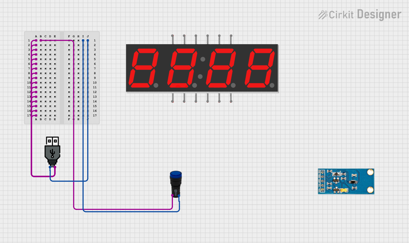
This document provides a detailed overview of a simple circuit consisting of a light sensor, a pilot lamp, a 7-segment display, and a USB power source. The circuit is designed to power a pilot lamp using a USB power source.
Component List
Light Sensor
- Pins: VCC, SCL, SDA, ADD, GND
- Description: A sensor used to detect light levels.
- Purpose in Circuit: Not specified.
Pilot Lamp Blue
- Pins: x1, x2
- Description: A blue indicator lamp.
- Purpose in Circuit: Indicates power status.
7 Segment Display (4 Digit)
- Pins: 1, A, F, 2, 3, B, G, 4, C, DP, D, E
- Description: A 4-digit 7-segment display.
- Purpose in Circuit: Not specified.
USB Power
- Pins: +, -
- Description: A USB power source.
- Purpose in Circuit: Provides power to the circuit.
Wiring Details
Light Sensor
- Pins: VCC, SCL, SDA, ADD, GND
- Connections: Not connected in this circuit.
Pilot Lamp Blue
- Pins: x1, x2
- Connections:
- x1 is connected to USB power +
- x2 is connected to USB power -
7 Segment Display (4 Digit)
- Pins: 1, A, F, 2, 3, B, G, 4, C, DP, D, E
- Connections: Not connected in this circuit.
USB Power
- Pins: +, -
- Connections:
- + is connected to Pilot lamp blue x1
- - is connected to Pilot lamp blue x2
Code
No microcontroller code is provided for this circuit.
This document provides a comprehensive overview of the components and their connections within the circuit. The pilot lamp is powered by the USB power source, while the light sensor and 7-segment display are not connected in this particular setup.