
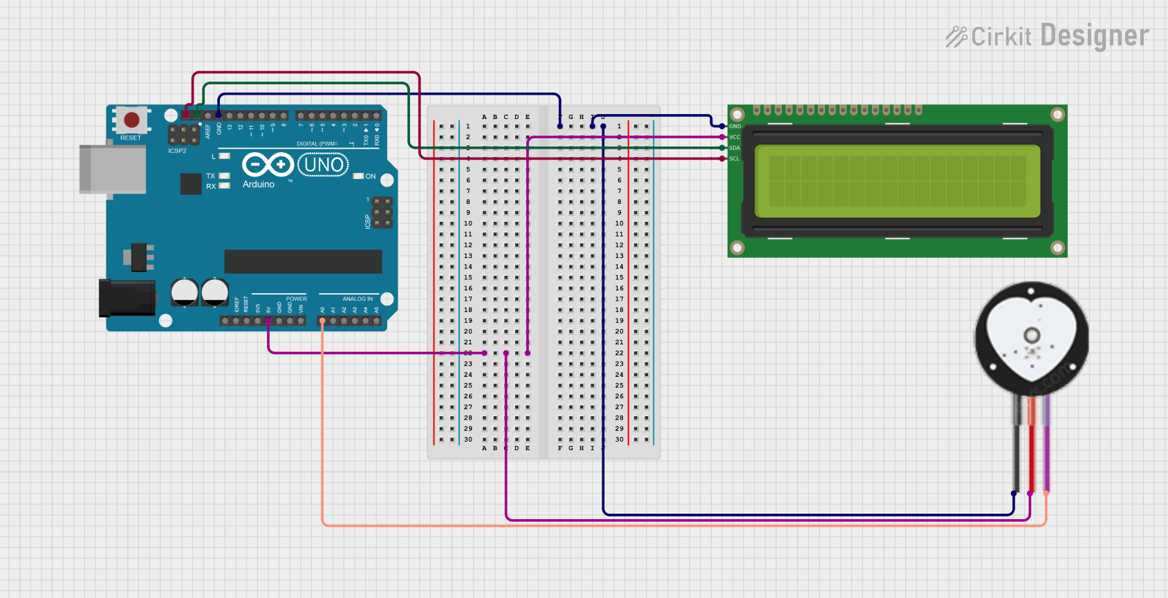
Heartbeat Monitoring Circuit Documentation
Summary
This document provides a detailed overview of a heartbeat monitoring circuit. The circuit consists of an Arduino UNO microcontroller, a 16x2 I2C LCD display, and a heart pulse sensor. The Arduino UNO reads the pulse sensor data and displays the heartbeat rate (BPM) on the LCD. Additionally, an LED is used to indicate heartbeat detection.
Component List
Arduino UNO
- Description: A microcontroller board based on the ATmega328P.
- Pins: UNUSED, IOREF, Reset, 3.3V, 5V, GND, Vin, A0, A1, A2, A3, A4, A5, SCL, SDA, AREF, D13, D12, D11, D10, D9, D8, D7, D6, D5, D4, D3, D2, D1, D0
16x2 I2C LCD
- Description: A 16x2 character LCD display with I2C interface.
- Pins: GND, VCC, SDA, SCL
Heart Pulse Sensor
- Description: A sensor used to detect heartbeats.
- Pins: GND, VCC, SIGNAL
Wiring Details
Arduino UNO
- GND: Connected to GND of 16x2 I2C LCD and Heart Pulse Sensor.
- 5V: Connected to VCC of 16x2 I2C LCD and Heart Pulse Sensor.
- A0: Connected to SIGNAL of Heart Pulse Sensor.
- SCL: Connected to SCL of 16x2 I2C LCD.
- SDA: Connected to SDA of 16x2 I2C LCD.
16x2 I2C LCD
- GND: Connected to GND of Arduino UNO.
- VCC: Connected to 5V of Arduino UNO.
- SCL: Connected to SCL of Arduino UNO.
- SDA: Connected to SDA of Arduino UNO.
Heart Pulse Sensor
- GND: Connected to GND of Arduino UNO.
- VCC: Connected to 5V of Arduino UNO.
- SIGNAL: Connected to A0 of Arduino UNO.
Code Documentation
#include <Wire.h>
#include <LiquidCrystal_I2C.h>

LiquidCrystal_I2C lcd(0x27, 16, 2); // Adjust if necessary
const int sensorPin = A0;      // Pulse sensor input
const int enableButton = 2;    // Button input for AND gate
const int ledPin = 13;         // LED output via OR gate
const int threshold = 550;     // Threshold for pulse detection

int bpm = 0;
int lastReading = 0;
int currentReading = 0;
unsigned long lastBeatTime = 0;
bool heartbeatDetected = false;

void setup() {
  lcd.begin(16, 2);
  lcd.backlight();
  lcd.print("Heartbeat Monitor");

  pinMode(sensorPin, INPUT);
  pinMode(enableButton, INPUT_PULLUP);
  pinMode(ledPin, OUTPUT);
  Serial.begin(9600);
}

void loop() {
  // Read pulse sensor
  currentReading = analogRead(sensorPin);
  heartbeatDetected = (currentReading > threshold && lastReading <= threshold);

  if (heartbeatDetected) {
    unsigned long currentTime = millis();
    if (lastBeatTime != 0) {
      int beatInterval = currentTime - lastBeatTime;
      bpm = 60000 / beatInterval;
    }
    lastBeatTime = currentTime;
    digitalWrite(ledPin, HIGH); // OR gate LED indication

    // AND gate for LCD display
    if (digitalRead(enableButton) == LOW) {
      lcd.setCursor(0, 1);
      lcd.print("BPM: ");
      lcd.print(bpm);
    }
  } else {
    digitalWrite(ledPin, LOW);
  }

  lastReading = currentReading;
  delay(10); // Smooth signal
}
This code initializes the LCD and sets up the necessary pins for the pulse sensor, button, and LED. In the main loop, it reads the pulse sensor data, detects heartbeats, calculates the BPM, and updates the LCD and LED accordingly. The button is used to enable or disable the BPM display on the LCD.