
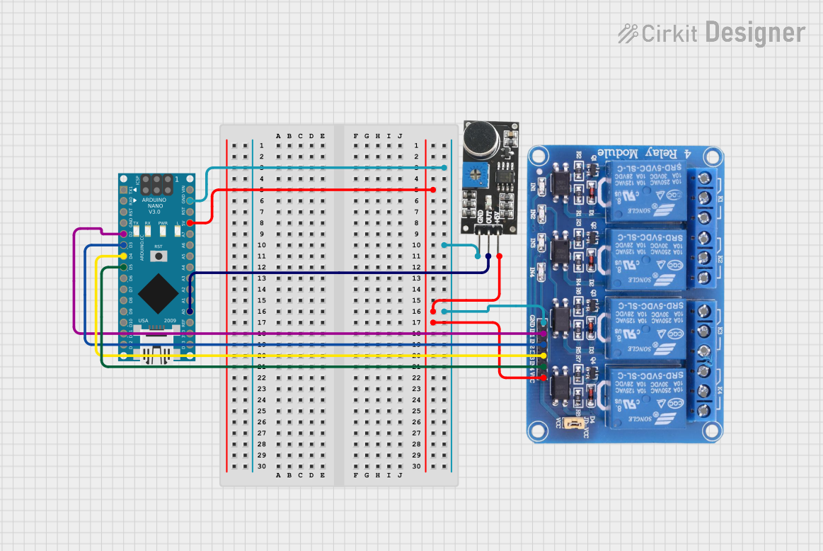
Circuit Documentation
Summary
This circuit is designed to control a 4-channel relay module based on sound levels detected by a sound sensor. The Arduino Nano microcontroller reads the output from the sound sensor and activates the relays accordingly. The relays can be activated in different configurations depending on the detected sound level, which is categorized into NORMAL, LOW, MEDIUM, and HIGH levels. The sound sensor output is connected to the analog pin A0 of the Arduino Nano, while the relay control pins are connected to digital pins D2, D3, D4, and D5.
Component List
Relay 4 Channel 5v
- Description: A 4-channel relay module capable of controlling multiple high-power circuits with a 5V signal.
- Pins: GND, IN1, IN2, IN3, IN4, VCC, COM1, COM2, COM3, COM4, NO1, NO2, NO3, NO4, NC1, NC2, NC3, NC4
Sound Sensor
- Description: A sensor that detects sound levels and outputs a signal proportional to the sound intensity.
- Pins: 5V +, OUT, GND
Arduino Nano
- Description: A compact microcontroller board based on the ATmega328P, suitable for embedding into projects.
- Pins: D1/TX, D0/RX, RESET, GND, D2, D3, D4, D5, D6, D7, D8, D9, D10, D11/MOSI, D12/MISO, VIN, 5V, A7, A6, A5, A4, A3, A2, A1, A0, AREF, 3V3, D13/SCK
Wiring Details
Relay 4 Channel 5v
- GND: Connected to GND on Arduino Nano
- VCC: Connected to 5V on Arduino Nano
- IN1: Connected to D2 on Arduino Nano
- IN2: Connected to D3 on Arduino Nano
- IN3: Connected to D4 on Arduino Nano
- IN4: Connected to D5 on Arduino Nano
Sound Sensor
- 5V +: Connected to 5V on Arduino Nano
- OUT: Connected to A0 on Arduino Nano
- GND: Connected to GND on Arduino Nano
Arduino Nano
- 5V: Provides power to Relay 4 Channel 5v and Sound Sensor
- GND: Common ground for Relay 4 Channel 5v and Sound Sensor
- D2: Controls IN1 on Relay 4 Channel 5v
- D3: Controls IN2 on Relay 4 Channel 5v
- D4: Controls IN3 on Relay 4 Channel 5v
- D5: Controls IN4 on Relay 4 Channel 5v
- A0: Reads the output from the Sound Sensor
Documented Code
/*
 * This Arduino Sketch controls a 4-channel relay module based on sound levels
 * detected by a sound sensor. The relays are activated sequentially based on
 * the sound level. The sound sensor output is read from analog pin A0, and the
 * relays are controlled via digital pins D2, D3, D4, and D5.
 *
 * Sound levels:
 * - Normal: No relays activated
 * - LOW: Relay 1 activated
 * - MEDIUM: Relay 1 and 2 activated
 * - HIGH: All relays activated
 */

const int soundSensorPin = A0; // Sound sensor output connected to A0
const int relayPins[] = {2, 3, 4, 5}; // Relay control pins
const int numRelays = 4; // Number of relays

void setup() {
  // Initialize serial communication
  Serial.begin(9600);
  // Initialize relay control pins as outputs
  for (int i = 0; i < numRelays; i++) {
    pinMode(relayPins[i], OUTPUT);
    digitalWrite(relayPins[i], HIGH); // Turn off relays initially
  }
}

void loop() {
  int soundLevel = analogRead(soundSensorPin); // Read sound level
  Serial.println(soundLevel); // Print sound level to serial monitor

  // Determine which relays to activate based on sound level
  if (soundLevel > 600) { // HIGH sound level
    for (int i = 0; i < numRelays; i++) {
      digitalWrite(relayPins[i], LOW); // Activate all relays
    }
  } else if (soundLevel > 400) { // MEDIUM sound level
    digitalWrite(relayPins[0], LOW); // Activate relay 1
    digitalWrite(relayPins[1], LOW); // Activate relay 2
    digitalWrite(relayPins[2], HIGH); // Deactivate relay 3
    digitalWrite(relayPins[3], HIGH); // Deactivate relay 4
  } else if (soundLevel > 200) { // LOW sound level
    digitalWrite(relayPins[0], LOW); // Activate relay 1
    digitalWrite(relayPins[1], HIGH); // Deactivate relay 2
    digitalWrite(relayPins[2], HIGH); // Deactivate relay 3
    digitalWrite(relayPins[3], HIGH); // Deactivate relay 4
  } else { // Normal sound level
    for (int i = 0; i < numRelays; i++) {
      digitalWrite(relayPins[i], HIGH); // Deactivate all relays
    }
  }

  delay(100); // Small delay to avoid rapid switching
}
This code is designed to be uploaded to the Arduino Nano microcontroller. It initializes the serial communication for debugging purposes and sets up the relay control pins. The main loop reads the sound level from the sound sensor and activates the relays based on predefined thresholds.