
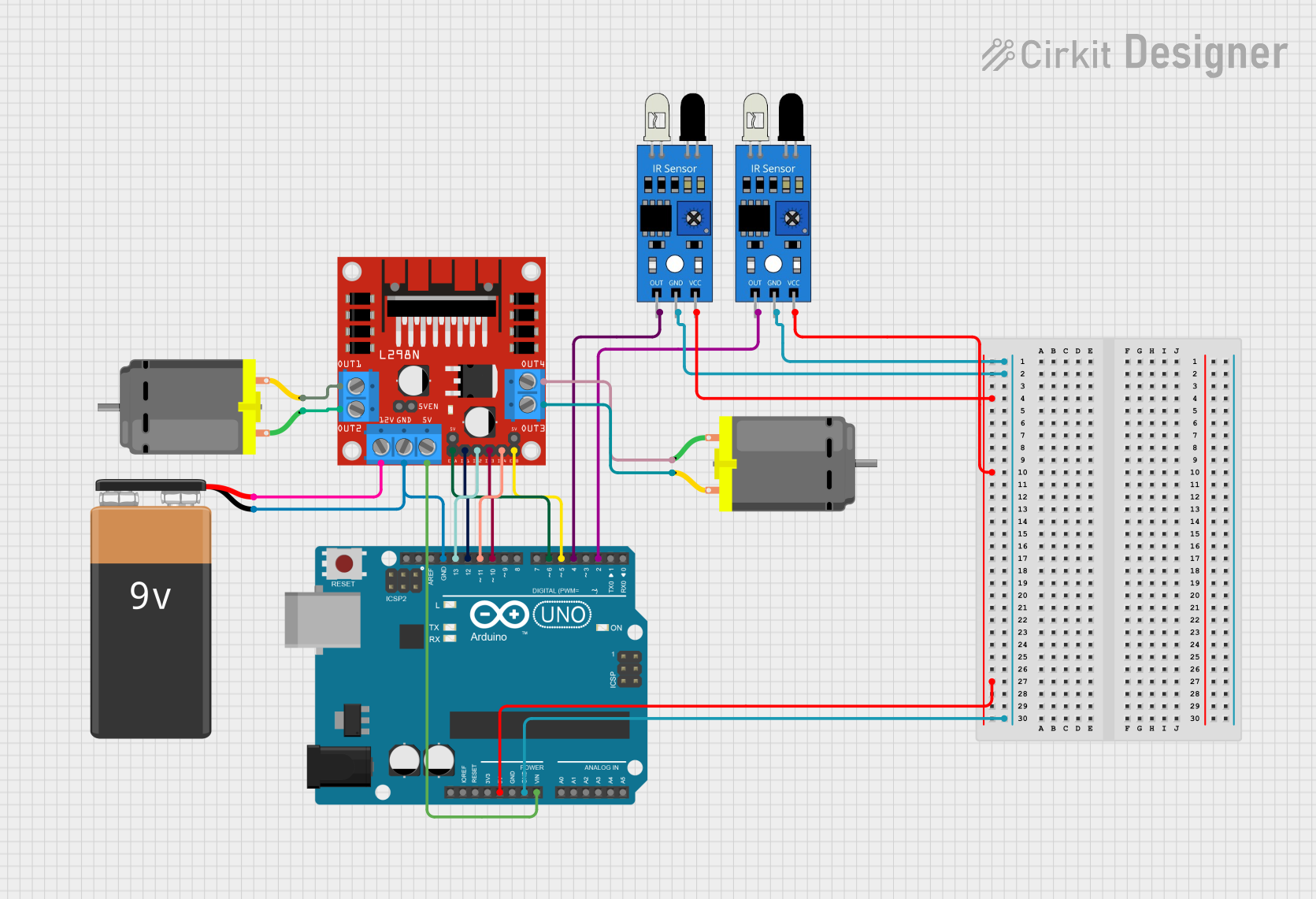
Circuit Documentation
Summary of the Circuit
This circuit is designed to control two DC motors using an Arduino UNO microcontroller and an L298N DC motor driver. Additionally, two IR sensors are included for input sensing. The Arduino UNO is responsible for processing the signals from the IR sensors and driving the motors through the L298N motor driver based on the sensor inputs. The motors are powered by a 9V battery, which also supplies power to the motor driver. The Arduino UNO is powered through its Vin pin, which is connected to the 5V output of the motor driver, and it controls the motor driver using several of its digital I/O pins.
Component List
IR Sensor
- Pins: out, gnd, vcc
- Description: An infrared sensor used for detecting objects or motion. It typically outputs a digital signal indicating the presence of an object within its sensing range.
DC Motor
- Pins: pin 1, pin 2
- Description: An electric motor that runs on direct current (DC) electricity. It has two terminals for power connection.
Arduino UNO
- Pins: UNUSED, IOREF, Reset, 3.3V, 5V, GND, Vin, A0-A5, SCL, SDA, AREF, D0-D13
- Description: A microcontroller board based on the ATmega328P. It has digital input/output pins, analog inputs, a USB connection for programming, and power jacks.
L298N DC Motor Driver
- Pins: OUT1, OUT2, 12V, GND, 5V, OUT3, OUT4, 5V-ENA-JMP-I, 5V-ENA-JMP-O, +5V-J1, +5V-J2, ENA, IN1, IN2, IN3, IN4, ENB
- Description: A dual H-bridge motor driver that can drive two DC motors or one stepper motor. It can handle a substantial current and voltage and is controlled by logic signals.
9V Battery
- Pins: -, +
- Description: A standard 9V battery used to provide power to the circuit.
Wiring Details
IR Sensor
- out: Connected to a digital I/O pin on the Arduino UNO for object detection signaling.
- gnd: Connected to the ground (GND) pin on the Arduino UNO.
- vcc: Connected to the 5V power supply from the Arduino UNO.
DC Motor
- pin 1 and pin 2: Connected to the output pins of the L298N motor driver to receive power and control signals for motor operation.
Arduino UNO
- GND: Common ground for the circuit.
- 5V: Provides power to the IR sensors.
- Vin: Receives 5V from the L298N motor driver to power the Arduino UNO.
- Digital I/O Pins (D2, D4, D5, D6, D10, D11, D12, D13): Control the L298N motor driver and receive signals from the IR sensors.
L298N DC Motor Driver
- 5V: Provides power to the Arduino UNO.
- GND: Connected to the negative terminal of the 9V battery and the GND of the Arduino UNO.
- IN1, IN2, IN3, IN4: Receive control signals from the Arduino UNO to drive the motors.
- ENA, ENB: Enable pins for the motor driver, controlled by the Arduino UNO.
- OUT1, OUT2, OUT3, OUT4: Connected to the DC motors to provide controlled power for motor operation.
- 12V: Connected to the positive terminal of the 9V battery to power the motors.
9V Battery
- -: Connected to the GND of the L298N motor driver.
- +: Connected to the 12V input of the L298N motor driver to power the motors.
Documented Code
Arduino UNO Code (sketch.ino)
void setup() {
  // put your setup code here, to run once:

}

void loop() {
  // put your main code here, to run repeatedly:

}
The provided code is a template with empty setup() and loop() functions. The setup() function is intended to contain initialization code that runs once when the Arduino is powered on or reset. The loop() function is meant to contain the main logic of the program, which runs repeatedly as long as the Arduino is powered.
Additional Notes
- The code for the Arduino UNO is currently a placeholder and needs to be completed with the logic for reading the IR sensor inputs and controlling the DC motors via the L298N motor driver.
- The actual behavior of the motors will depend on the implementation of the control logic within the
loop()function. - The IR sensors' outputs are connected to digital pins D2 and D4 on the Arduino UNO. These pins should be configured as inputs in the
setup()function. - The motor driver's control pins (IN1, IN2, IN3, IN4, ENA, ENB) are connected to digital pins D5, D6, D10, D11, D12, and D13 on the Arduino UNO. These pins should be configured as outputs in the
setup()function.